Student Projects
Bird with Flapping Wings Powered by CFM
Project Video
Team Members

Team Members:
Alikhan Zhaxylykov, Christopher Anthony, 李奕飞 Yifei Li, 焦丰荃 Fengquan Jiao, 张睿尧 Ruiyao Zhang
Instructors:
Irene Wei,Shane Miguel Johnson
Project Description
-
Problem

Bird lovers and toy companies have long been keen on designing a toy bird that can flap its wings.Since birds with flapping wings is beautiful and vigorous.

But the preexisting products on the market all have some drawbacks. The first kind of these flapping bird toys are the electric ones. The problem of these toys is that: First, since the electronic components are very fragile, a single crush on the ground may cause the toy to fail. Second, it needs electricity, so users either need to charge it or replace the battery from time to time, which is quite annoying. Third, they’re quite expensive. Some toys sell at more than 200 dollars, it’s quite luxurious and cannot be afforded by everyone.
And the other kind of the flapping bird toys is the Traditional human-powered toy birds. they often use spiral springs as the power source and use gears to change the circular movement of the spiral spring to the linear movement of the flapping wings. The first drawback of the traditional mechanism is that most of the birds don’t have an escapement mechanism, so the energy stored can’t be slowly released, which results in its flapping too fast at first while too slow at the end.
Another thing that a spiral spring’s torque increases when we wind it up. So it is not friendly to the young kids because their wrist and fingers are not strong and dexterous enough to handle it.
-
Concept Generation
To solve the problem of the preexisting flapping birds, we come up with the idea of combining a linear escapment mechansim with a CFM. First it will be fully-human-powered, so all of the problems of the electric birds can be eliminated; Secondly a linear escapement can let the power stored in CFM releases slowly and steadly, thus creating stable flapping speed; Thirdly a CFM's force won't keep rising when we compress it, so we can control the force to be very small so that young kids can have enough strengh to handle it. And since it is linearly compressed, it requires no dexterity, which makes it friendly to young kids.
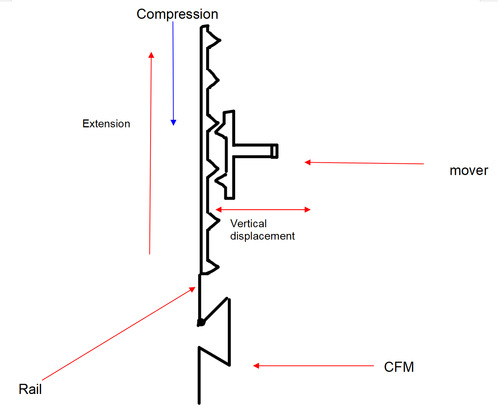
Fig. Early concept
-
Design Description
Below is the concept diagram of our design.
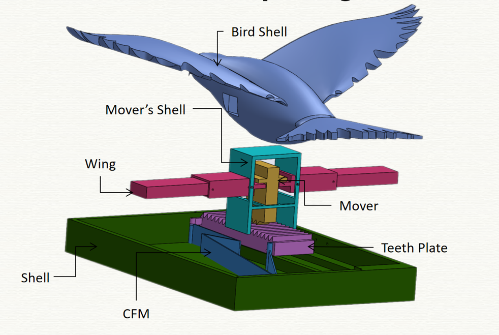
It mainly consists of three mechanisms: Constant Force Mechanism(CFM), linear escapement(Teeth Plate and Mover), and wing mechanism.
CFM serves as the power source of the product. We adjust it to produce a relatively constant force that is small enough for young children to play with. It has two ends: a fixed end and a moving end. We move the moving end to approach the fixed end to compress it, and then release the moving end to let it move backward. Teeth Plate is connected to the moving end of the CFM, so it can move back and forth.
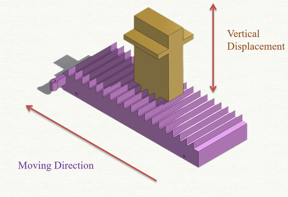
Since there are teeth on both Teeth Plate and Mover, when the CFM is released and Teeth Plate starts to moving, the teeth on Teeth Plate can impose a force on Mover to lift it up. We put springs on the top of the mover to press it down, so that it can always touches Teeth Plate and provide a force backward to slow the moving of Teeth Plate to reach the effect of linear escapement.
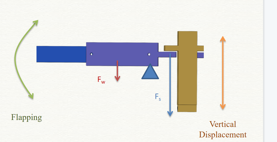
The wing mechanism is a lever: the wing is pinned on the shell near Mover where there's a pivot. As is mentioned previously, there are springs that press the mover down, so mover can impose a force on the lever that makes it rotate clockwise. Notice that this force is way bigger than the weight of the wing, so Mover can control the rotation or flapping of the wing: when it goes down, the wing goes up, and vice versa.
-
Validation
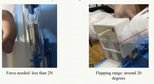
Since there are some errors with our design and we don't have enough time to do another 3D printing to fix it, by symposium, bird cannot flap its wing using the enegry from CFM. Although we can't test how long can it keep flapping, the force needed to compress CFM and the range of wing's flapping can be measured: the force needed is only less than 2 newtons, so it will be very easy for young kids to handle; The angle of the flapping is around 20 degrees, which is similar to the real birds' flapping.
-
Modeling and Analysis
The errors of our design is that the force that the teeth impose on Mover will cause Mover to stuck.
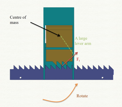
As you can see in the picture above, the teeth plate imposes a force Ft on the mover. The distance between the mover’s centre of mass and the force point, which is the lever arm, is really large. So the mover has a large torque and it rotates anticlockwise rather than rises vertically, which causes the mover to have a smaller vertical displacement than we thought, so it cannot leave the teeth plate, and causes the stuck.
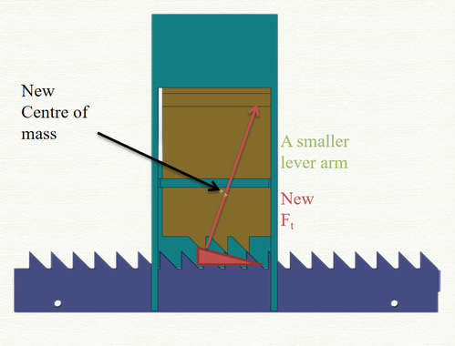
To fix the problem, we need to reduce the torque of Mover. Since the force imposed on Mover cannot be adjusted to be smaller, we can shorten the lever arm. The first method is to reduce the slope of the teeth on the teeth plate. As you can see in the picture above, in this case Ft will be pointing near to the centre of mass. And another way is to lower the mover’s centre of mass by adding some weights on the bottom of it. Both of the ways can help reduce the lever arm of Ft on the mover, so the torque can be small enough and there will be nearly no rotation.
-
Conclusion
In this project, we combine the CFM with a linear escapement and design a wing mechanism to create a toy bird that is beautiful and can be appreciated by people of different generations. And this kind of mechanism can be applied to many other products like a linear kinetic sculpture or other biometric products such as a swimming dolphin. There are definitely several improvements that we can make. First we should decrease the torque generated by teeth, which is already discussed in the analysis part. Secondly, we can Use vibration to create the flapping rather than use a mover to directly pull it up and down, so that it will have better energy efficiency. Finally, we can apply another kind of CFM that occupies less space with the same maximum displacement, so that the pedestal size will be smaller.
-
Acknowledgement
Here we want to thank Professor Shane, Professor Irene, TA Haomiao Xu, TA Xiyuan Wang, TA Ruiqi Xu and TA Seungyeon Yang for their help. It is your effort, patience and encouragement that prompt us to keep improving our projuct. We can't imagine how tough the project would have been without you.
-
Reference
[1] Ou, H., Yi, H., Qaiser, Z., Ur Rehman, T., Johnson, S, A Structural Optimization Framework to Design Compliant Constant Force Mechanisms With Large Energy Storage, in: ASME. J. Mechanisms Robotics, April 2023.
[2] R. Besuchet, Y. Civet, Y. Perriard, A novel electronically-controlled linear escapement mechanism, in: 2014 17th International Conference on Electrical Machines and Systems (ICEMS), 2014, pp. 2204-2210, pp.