Student Projects
Deflectometry-Based Surface Inspection System
Project Video
Team Members

Team Members:
姬海朝 Haichao Ji, 姚家冀 Jiaji Yao, 钟仕杰 Shijie Zhong, 吴诗媛 Shiyuan Wu, 吴雨瞳 Yutong Wu
Instructors:
Jigang Wu,Yulian He
Project Description
-
Problem

In modern industry, surfacemeasure-ment is crucial, through whichpeople can precisely determine the surface roughness and surface profile. Phasemeasuring deflectometry (PMD) is a famous deflectometry technique based on phasecalculation. The existing PMD models cannot simultaneously achieve highprecision, fast detection and simple operation. This project raised a potentialsingle-screen and single displayer system that can detect the surface informationwith high precision in a short cycle time.
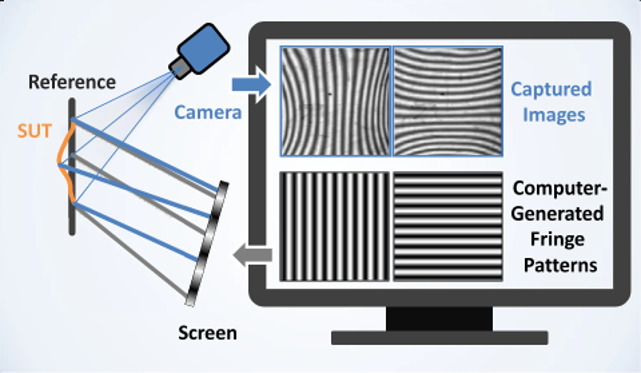
Fig.1 Deflectometry-based surface inspectionsystem [1]
-
Concept Generation
The PMD model mainly contains three parts: a camera, tested objectand a displayer. The camera captures the displayer image reflected from thesurface of the tested object. After adding a glass, the optical path will change andthe image will be shifted.With the two groups of points, we can determine the accurate surface normalvector. And therefore, the whole surface situation can be known.
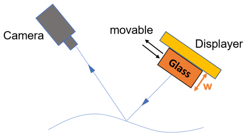
Fig.2 Schematic design picture
-
Design Description
The design has 2 parts. First is the base. To fix the components,we use wooden board and blocks to make a base. The second part is theequipment. In application, the distance between camera and object, displayerand object is decided according to the size of the object and displayer. In ourtest, we choose cell phone as tested object so we set both thedistance 15cm. The camera, object and displayer are placed at a 45 degree angle. A trough for glassis designed between the object and displayer.
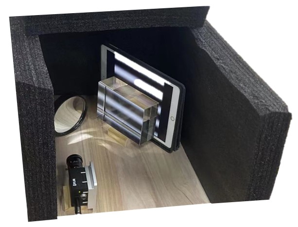
Fig.3 The whole set-up system
-
Validation
Validation Process:
For repeatability, 3 measurements are performed on a specificobject. With fixed focus length of camera lens, object distance and reflectionangle, we check the difference between the measured results. If the count ofdifferent pixels is less than 1/10 of the image size, then we consider it asfulfilling the requirement. Some other specifications can also be verified using easyexperiments.
Validation Results:
According to validation part, most specifications can be met.
√ Cycle time ≤ 4s
√ Size of measured object = 25cm2
√ Size of system ≤ 0.25m2
√ Cost ≤ 500RMB
• Height error RMS ≤ 1/2 pixel size
• Difference between twotrials on the same object ≤ 1/10 pixel size
√ means having been verifiedand means to be determined.
-
Modeling and Analysis
A python code is built to transform the 2D image phase shift to thesurface normal vector at each point. Then the surface defects can be calculatedbased on the normal vectors. A matlab code is developed tosimulate the phase shift process and helps to optimize the design.

Fig.4 Matlab simulated phase shift of aspherical surface (left is the image taken without glass, the right is theimage taken with glass of 5cm thickness)
-
Conclusion
Movable-medium based deflecto-metry system can be used fordetect-ing surface defects. The keypoint is to optimize the width of the medium (glass). And also, the accuracy and speed ofthe motion control system is very important to the image generation.
-
Acknowledgement
Faculty Advisor: Jigang Wu and Peisen Huang from UM-SJTU JointInstitute
Di Wu and Zheng Huang from MEGA PHASE technology.
-
Reference
[1] Huang, Lei, et al. Review of phase measuring deflectometry. Optics andLasers in Engineering 107 (2018): 247-257.