Student Projects
Design of Carbon Dioxide Direct Air Capture Contactor
Project Video
Team Members

Team Members:
殷亿玮 Yiwei Yin 顾佳栋 Jiadong Gu 罗梁宇 Liangyu Luo 崔逸群 Yiqun Cui 杨林然 Linran Yang
Instructors:
Yulian He
Project Description
-
Problem

Introduction
Introduction of DAC
Since the Industrial Revolution, the amount of CO2 in the air has been rising continuously, reaching a staggering 418 ppm recently \cite{3}. This inevitably brings serious environmental problems, such as continuously rising temperatures, melting glaciers, rising sea levels, extreme weather, etc. The uncontrolled increase for CO2 in atmospheric is largely attributable to human activities, and fossil fuel burning accounts for nearly 70% of it \cite{3}. The Paris Agreement proposes the goal of carbon neutrality, which is to achieve net zero emissions \cite{11}. This not only requires to reduce the source of carbon dioxide emissions, but also asks for removing and recovering carbon dioxide through man-made means using carbon dioxide capture and utilization technologies.
This technology is called CCUS, which stands for carbon dioxide capture, utilization, and storage. As shown in Fig.ref{fig:1}
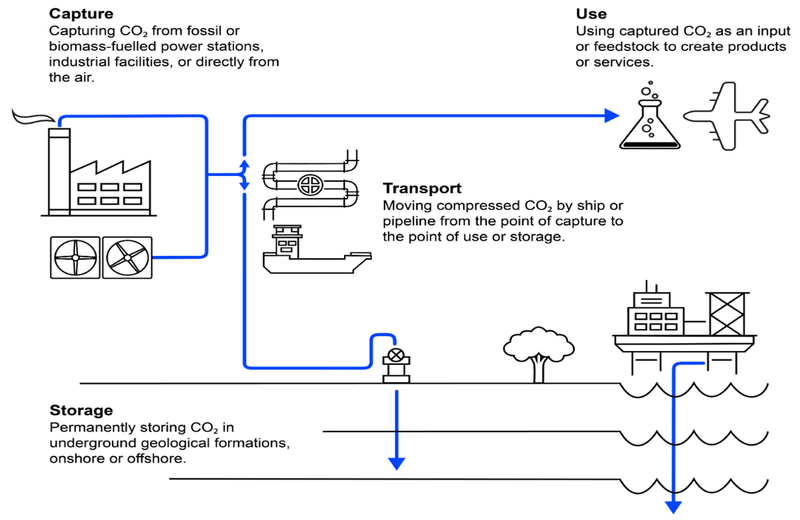
, CCUS is a set of technologies, and there are different types of CCUS projects depending on the underlying technology of the industry chain. A portion of the CO2 is sequestered, which involves further safe and long-term storage of the captured carbon underground. Utilization generally refers to the use of carbon dioxide to produce products, such as methanol and methane, or for direct physical applications, such as the production of carbonated beverages. The first step in CCUS is generally to capture carbon dioxide from large industrial plants or fossil fuel-based power plants. This method of point source capture is inexpensive, and the technology is now very mature. However, point source capture means that the location of carbon capture is limited to large factories, and the captured CO2 need to be compressed and transported before utilization, driving up costs even further. Therefore, a method that can capture CO2 directly from the air is proposed, that is, direct air capture (DAC).
For a long time, it was thought that DAC was not feasible because of the extremely low CO2 concentration in the air. Compared with the concentration of CO2 captured by point sources, the high concentration can reach 50-90%, and the low concentration can also be 5-15%, while the concentration of CO2 in the air is only about 0.04%. The extremely diluted CO2environment leads to significant technical hurdles and high capture costs. The cost of DAC is calculated to be about 600 dollars per ton \cite{3}, which is a very large number compared to the tens of dollars per ton of point source capture. Lackner first proposed the concept and possibilities of DAC in the 1990s \cite{5}. Later, he proved in the thermodynamic category that DAC is not constrained by the thermodynamic limit, which provided support for the feasibility of DAC \cite{6}. In 2009, David Keith turned this theory into reality, and started a company called Carbon Engineering (CE), which focuses on testing DAC. In 2015, CE solved key technical problems \cite{7}. Now, CE has been piloted around the world, and several large projects are under construction. CE is also at the forefront of many start-ups.
Compared with traditional technologies, DAC can achieve negative emissions. Combined with photovoltaic or nuclear energy, DAC is significant in energy conservation and emission reduction. Besides, the location of DAC is flexible enough to allow carbon capture on unusable land such as deserts. DAC has great potential, and according to the world organization for energy, DAC will expand to nearly 60 million tons of CO2 per year until 2030 \cite{3}. This proves that DAC has research value.

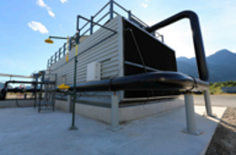
The two pictures show the design appearance of DAC of David Keith and his Carbon Engineering\cite{1}. DAC is mainly consisting of four-unit operations: contactor, pellet reactor, calciner and steam slaker. Contactor brings ambient air in contact with the capture solution. Carbonate ion is removed from solution by causticization in the pellet reactor. Calciner is a large steel vessel lined internally with refractory brick which retrieve CO2. For the steam slaker, refractory lined bubbling or turbulent fluid bed that is fluidized by recirculating steam flow, do something with the chemicals. Our design also refers to this structure, and the overall structure is divided into two processes of adsorption and desorption.
However, the DAC field as a whole is still in its infancy. There are mostly startups on the market, especially in China, there are no outstanding companies in this field. Besides, most of the designs of these startups are flawed, making it difficult to promote DAC on a large scale in the market. For example, many companies use liquid alkali adsorbents with high adsorption strength, but high bonding energy will make desorption more difficult; The open-air fan, as a blast device, is difficult to avoid the return of purified air to the intake, which reduces the adsorption efficiency. Therefore, based on these flaws, we hope to produce a proof-of-concept model to prove the principle of adsorbing carbon dioxide from the air, so as to serve as a demonstration for the large-scale popularization of DAC.
This project designs a small-scale model of a direct air capture device using a more commercially viable solid amine adsorbent, and capable of capturing more than 100 mg of CO2 per day from the air, which is a reasonable assumption according to equilibrium thermodynamics and a few available data. At present, the application of DAC is still in the startup and prototype stage, and more experimental data are needed to provide application support. As a small model, this project hopes to provide some reference value and data for the large-scale expansion of DAC applications.
Benchmark and Literature Review
During more than 20 years of continuous development of DAC, numerous companies and university research institutions have focused on amplifying laboratory results and gradually building up the demonstration scale of DAC in commercial plants in tiny trials, prototypes, and pilot trials.
Carbon Engineering and Climeworks are early starters and have built commercial demonstration plants. Carbon Engineering and its partners plan to build the first large-scale commercial plant in 2023. Up to 1 Mt of CO2 per year for enhanced oil recovery. Carbon Engineering started early and has already built a commercial plant. The adsorbent they used was a hot solution of potassium hydroxide. Their capacity is 1 t/day, lower than other companies, but the cost is also lower to 35-50 dollars per day. Climeworks uses the solid amine as the adsorbents. They increased the capacity to 2.47 t per day, but the corresponding cost increased to about 92 dollars per day.
Then the global thermostat, which traps CO2 using a ceramic-based metal-organic framework, ramped up to a capacity of 10.96 T per day. However, due to the difficulty of preparing MOF, the cost can reach up to 160 dollars per day.
Finally, Carbfix, the largest DAC and enhanced weathering coupling system in the world, has increased the adsorption capacity to 30.5 T per day. And it only costs 48 dollars per day. Carbfix built the world's largest DAC and enhanced weathering coupling system in 2017 and has a ground-breaking deal with Climeworks to build a 4,000 T per year capture plant at the Geothermal Park in Iceland. Zhejiang University has developed a 30 kg per day miniaturized DAC prototype for greenhouses, using a variable humidity regeneration process to achieve efficient capture and concentration of CO2 from air sources and supply to agricultural greenhouses with integrated equipment and technology.
On the other hand, apart from the overall developing trend, we took a step further and conducted a literature study regarding the applicable adsorbents in the market. Generally speaking, adsorbents, which are utilized to fulfill the goal of carbon capture, could mainly be divided into two categories.
The first category is the liquid adsorbents. This includes the alkali hydroxide solutions, aqueous amino acid, etc\cite{2}. Main advantage of this category lies in its high efficiency in carbon fixing. However, many issues exist. Bearing high corrosivity, these strong base solutions might exert a negative effect on the environment. In addition, the poor stability of aqueous amino acid in air environment impairs the working efficiency to a certain extent.
The second one is the solid adsorbents. The most commonly-used one is the Amine-based solid adsorbent \cite{2}. With the relatively low regeneration temperature and low cost, it is favored by many researchers. Nevertheless, considering the limited surface area of the solid support, its capability to capture carbon is quite poor.
In view of all these remaining issues, the first step of this project is to figure out the most appropriate adsorbent so as to strike a balance between the interaction intensity of various adsorbents and their exposed surface areas. Only in this way could we ensure that we reach a maximum quantity of removed while lowering the operating costs as much as possible.
Design Creativity
1. Based on CE's KOH solution approach, we use a more stable and safer solid amine. On the one hand, solid amines are more stable and less corrosive to equipment. At the same time, solid adsorption avoids the high latent heat of adsorbing liquid heating, and can effectively solve the problems of difficult transportation and volatile liquid amine.
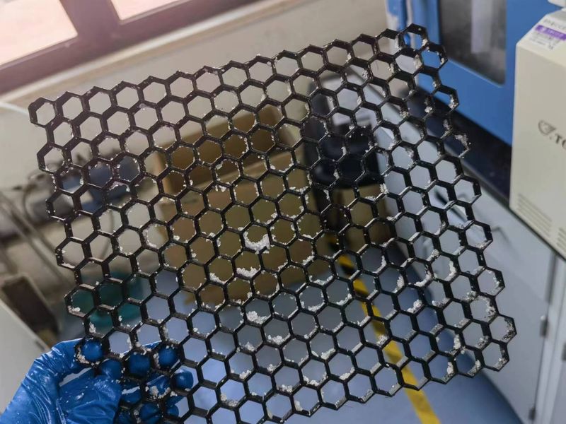
2. Our project innovatively uses honeycomb structures to maximize the contact area between the adsorbent and the air, as shown in Fig.\ref{fig:3}

. We make PEI/silica carbon dioxide solid adsorbent powders by ourselves, and make it into the slurry, and then coat it on the honeycomb bracket printed out of PVC.
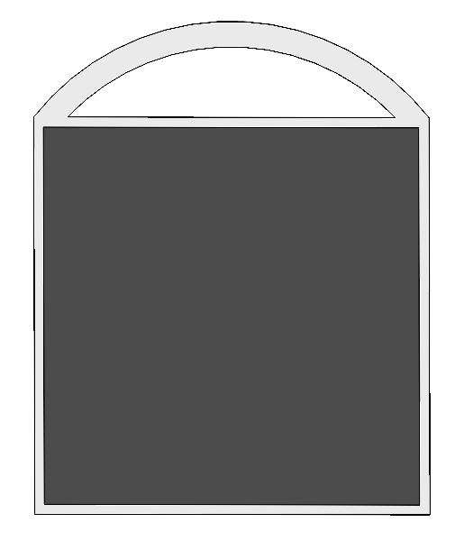
3. The adsorbing structure of our project has two filter units with hydrophobic components to separate the water molecules in air, so that during the adsorbing process, the mesoporous pores of adsorbent can directly contact with the CO2 molecular without being blocked by water molecules, enhancing the adsorbing efficiency. The two filter units are designed to be replaceable with a lifting handle for easy substitution. The filter is shown in Fig .\ref{filter}

.
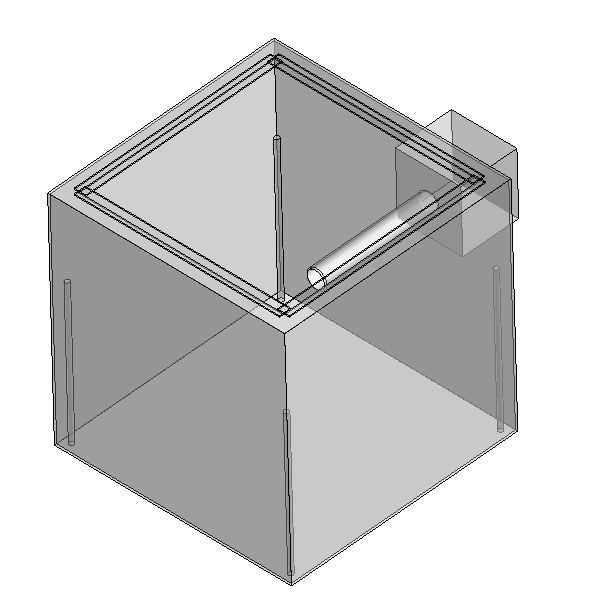
4. The honeycomb structure is put in a movable container with a cover on top. The whole container can be lifted by ropes and easily moved between the adsorption box and the desorption box. The cover of the container is designed to fit the open parts of the adsorption and desorption boxes well, in order to guarantee the vacuum tightness during desorption process. The container is shown in Fig. \ref{container}

.
Customer Requirements and Engineering Specifications
Customer Requirements
According to the marketing research and the requirements of our sponsor, the custom requirements are determined as:
Nice appearance: The prototype should be a well-formed cubic with an integrated circuit control.
Inexpensive: The cost of building and maintaining the prototype should be inexpensive, as well as the cost of adsorbing CO2.
High-efficiency: The prototype should have high-efficiency on adsorbing CO2.
Low energy consuming: The prototype should consume low energy since the goal is negative CO2 emission.
Can be scaled up: The prototype should be able to be scaled up since the goal is to capture CO2 in air, which requires an extreme large scale of device.
High safety: The CO2 adsorbent is alkaline, and the related temperature inside the prototype can be high, both of which might cause safety problems, so safety issues should be handle carefully.
Long-lasting: CO2 capture is a long-term process, so the prototype should be able to operate for long time.
CO2 adsorption: The function of the prototype is to adsorb CO2 directly from the air.
Engineering Specifications
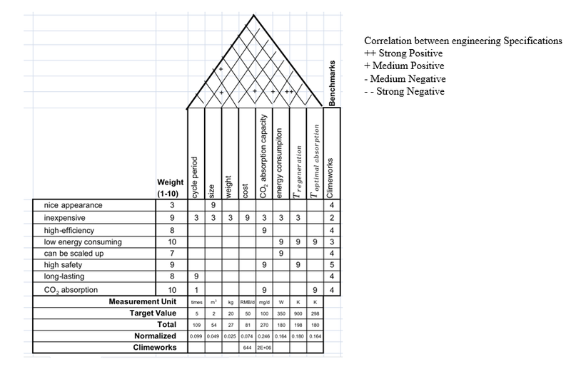
Engineering specifications are determined based on different custom requirements, and their relationships are shown in form of quality function deployment (QFD) in Fig.\ref{fig:4}
.
Cycle period: Cycle period is the times that a CO2 adsorbent can be recycled in use, it has strong connection to long-lasting since the more times an adsorbent can be recycled, the longer it can be used. The cycle period of our adsorbent is three times.
Size and weight: The size of the prototype is required by the sponsor, which should be no larger than 1 m × 1 m × 2 m. Based on the required size, the weight is estimated to be about 20 kg. Our prototype will have a 0.4 m × 0.4 m × 1.1 m, which is 0.176 m3, while the weight is around 10-15 kg. Both of the two values meet the target.
Cost: Since the product should be inexpensive, the cost of the prototype as well as the cost of CO2 adsorption should be low. The overall cost of the prototype target at 50 CNY per day, and the manufacture cost should be under 3500 CNY. The cost of our entire prototype will be around 2500 CNY. The daily electricity cost will be around 10 CNY, and daily cost of adsorbent and maintenance will be around 1 CNY.
CO2 adsorption capacity: This is the core of the prototype since it’s related to efficiency, safety and CO2 adsorption. The efficiency and adsorption have positive correlation to the capacity. Also, the capacity depends on the adsorbent, which has safety issues. The number is determined by the sponsor, which should be at least 100 mg per day.
Energy consumption: The goal of the product is to adsorb CO2 directly from air, while the overall CO2 emission should be negative. Also, the prototype should be able to be scaled up, which restrict energy consumption. Although the energy source can be clean and reproducible energy, the power of the prototype is expected to be lower than 350 W.
Adsorbent regenerating temperature and optimal adsorption temperature: The temperature of regeneration is targeted to be around 900 K. In fact, the regeneration part won’t be included in the prototype since the product focus on adsorbing CO2, energy is needed to regenerate, and the temperature affects safety, so the regenerating temperature shouldn't be too high. The optimal adsorption is targeted at around 298 K, which is around normal temperature, to guarantee the adsorbing process to be low energy consuming and easy to implement.
Relationships between engineering specifications have been labeled in QFD, and it also includes a benchmark which is the product of Clime works, and the related data and numbers are determined by the marketing research. The size of the prototype has medium positive correlation to the weight of the prototype, the cost of the prototype has medium positive correlation to the cycle period and the CO2 adsorption capacity of the adsorbent, the energy consumption of the prototype has strong positive correlation to the adsorbent regeneration temperature. Since optimal adsorption temperature is room temperature which needn't to be controlled by us, it won't have correlation with other engineering specifications.
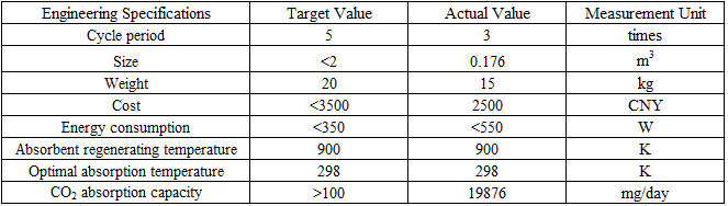
Fig. \ref{fig:5} shows the value of engineering specifications in detail:
-
Concept Generation
Concept Generation
As mentioned in the inroduction, Carbon Engineering build the first large-scale commercial plant in 2023 which use the liquid adsorbent to adsorb the carbon dioxide from the air. Their capacity is 1 t/day. They divide their device into 4 parts. Contactor brings ambient air in contact with the alkali capture solution. In the pellet reactor, carbonate ion is removed from solution by causticization. In the calciner, calcination of CaCO3 to produce CO2 is accomplished in an oxygen-fired. At last, heat from slaking is used to dry and preheat the pellets, yielding sufficient steam to sustain the slaking reaction \cite{1}.

However, under the project conditions, we have to redesign the size of the device and the type of the adsorbent to make it possible. We want to design a direct air carbon dioxide contactor device within the budget and site restriction. This device is composed of an adsorption box which is used to adsorb the carbon dioxide from air and a regeneration box which is used to regenerate the carbon dioxide from the adsorption box.

First, we applied a new concept, DAC, that captures CO2 directly from the air, which allows carbon capture to be done almost anywhere. Second, we use a solid amine adsorbent, which is both alkaline enough and has a low bond energy to make regeneration easy. At the same time, we use strong alkalis to modify the surface of solid amine and improve the capacity of the adsorbent. Moreover, the problem of water molecules blocking mesoporous pores was solved by adding hydrophobic components. Finally, we designed a beehive-like structure to maximize the contact area between the adsorbent and the air.
The selection of solid and liquid adsorbents is discussed above, which is the most central problem in our system. But it's not just about adsorbents. When the type of adsorbent is determined, we still have a series of systemic problems to solve. These problems depend on the aspects of contactor, reactor, calcination, and regeneration mentioned above. In order to promote adsorption, the solid adsorbent is formed in addition to a fan that acts like an internal suction of air. First of all, the most commonly used sheet molding is powerless against polymer-modified silica, and we have to abandon it. Another good option is grille or barrier, however since our solid adsorbents are powders as small as 40-80 nm, this method can greatly disrupt system stability. Therefore, in order to increase the contact area and ensure the life of the adsorption structure, we came up with a coating honeycomb solution.
Another equally important problem is that after adsorption, we need to help desorption of carbon dioxide to get a relatively pure stream of carbon dioxide. We chose to use a mixture of temperature swing adsorption and pressure swing adsorption, which is not common. The main reasons are as follows: Due to the extremely high energy consumption, it is difficult for industrial production to complete the temperature gradient. However, at this stage, our prototype can easily complete the desorption test with temperature, which will facilitate the manufacturing of the prototype. In contrast to temperature, industry is easier to achieve pressure changes, in our infrastructure, although we cannot complete the vacuum, but can reach a negative pressure state, which has a guiding significance for subsequent improvement.
Concept Selection Process
Scoring Matrices
Solid adsorbents VS. Liquid adsorbents
The core problem of this project is the selection of adsorbent. First, we should decide the form of adsorbent. From a theoretical point of view, there are three solutions: solid state, liquid state and gas state. The solid state and liquid state respectively use PEI/silica and KOH solutions as samples, while the gas state is basically only in the laboratory research stage due to its high price and harsh conditions of use, so there is no comparison here. It can be seen that in the selection of adsorbents, the two factors that account for the largest proportion are respectively energy consumption and capacity, and energy consumption is mainly related to the temperature of CO2 regeneration. The liquid adsorbent is too alkaline, and while it is easy to adsorb CO2, the very high bond energy makes desorption difficult, which usually requires high temperatures above 500 degrees Celsius. In addition, the heat capacity of liquids is higher than that of solids, and the latent heat will also cause excess energy loss. For capacity, the current data comes from two startups, climeworks and carbon engineering [1]. In recent years, the capacity of solid amines has been breaking through. However, because the DAC industry as a whole is still in its infancy, the current data is still relatively small, mostly theoretical values obtained by laboratory tests. Safety is also an important factor, as solids are much less toxic than liquids and are easier to transport and store. However, the recyclability of solid adsorbents is poor compared with the adsorbents, because most solid amine adsorbents are difficult to take into account the capacity and cycling stability, solid amine adsorbents including PEI are easy to decompose at high temperature, resulting in the loss of adsorbents.
In general, the advantages of solid adsorbents are far greater than disadvantages. In addition, the potential of solid adsorbents is much greater than that of liquid adsorbents, and the research on improving the capacity and stability of solid adsorbents is still ongoing. From the perspective of future potential, solid adsorbents are bound to surpass liquid adsorbents in the future to become the mainstream. Therefore, considering that the industry for DAC is in the early stages of development, and our model hopes to provide some support for the future direction of the industry, we finally decided to use solid adsorbents.
Powder-coated Honeycomb VS. Flaking-Shaping
After figuring out the specific adsorbent for adsorption, the next step is to find the appropriate supporter where the adsorbent could be applied to. Through conducting literature review, two approaches came to us, which were the flaking-shaping of silicon dioxide and PEI material, and powder-coated honeycomb respectively. The most apparent difference between these two methods lies in that the powder-coated honeycomb requires a 3D painted honeycomb as a supporter, thus adding to the total cost of the device. Generally speaking, there remains four criteria to consider while making comparisons between these two methods. The top two factors that need to be taken into account are both material and manufacture cost. Although by conducting flaking shaping, cost of the raw material for 3D painting could be saved, flaking shaping is not easy to realize. Considering the relatively high price of 3D painting, we strive to strike a balance between the comparatively lower cost and larger surface area, which is closely related to the adsorption capacity of the device. Detailed calculations utilizing the concept selection matrix is as illustrated in Table 2 above.
Pressure Swing Adsorption VS. Temperature Swing Adsorption VS. Combination
The common desorption methods are Pressure Swing Adsorption (PSA), Temperature Swing Adsorption (TSA), and the combination of these two method (TPSA). Since DAC is a startup technology and there are only few companies, while the real data of the related design criteria is hard to access, we determine the value and score of the criteria by Exp. Two main criteria of adsorption method are energy consumption and desorption efficiency. Industrial negative pressure is easy to realize, so the energy consumption of PSA is higher than TSA. The desorption efficiency is mainly related to the time of the desorption process. For PSA, the desorption process can be within a few minutes while TSA will take a few hours for desorption. To combine these two method, the cost will be higher, the energy consumption will stay between them and the desorption efficiency will be higher. Besides the criteria, practical problems should be taken into considered. For our prototype, it's impossible to adjust temperature and pressure at industrial level, and TPSA will lower the requirements. Also, the security will be higher since the temperature and pressure requirements will be more feasible. The rating of TPSA is the highest, so we determined to use TPSA as our adsorption method. The detailed data for our selection is illustrated in Table 3.
Heating Band VS. Heating Board
We pick out our heating method between heating band and heating board. The key affecting criteria are cost, energy consumption and highest temperature. The material cost of heating band is lower than heating board, while the manufacture cost of two methods stays consistent. Heating broad will consume lower energy than heating band while the highest temperature of it is lower. Since we need to heat our desorption environment to at least 333 K, the highest temperature is an important criteria. Considering all these facts, the rating of heating band is higher than heating board, so we decide to use heating band as our heating method. The detailed data is illustrated in Table 4.
PEI-Silica VS. Zeolite molecular sieve (ZSM) VS. MOFs (Metal-organic frameworks) VS. Alkaline earth metal (IIA)
According to our literature research, in order to decide which solid adsorbents we should use, we made some comparisons between a series of tested solid adsorbents. We set the standard for this comparison, mainly in the material price, processing price, adsorption efficiency and energy consumption of these four aspects. Of course, for these values, we set different weights, and use the experience value to evaluate the score, because they have very significant differences in various characteristics. Of these four comparisons, alkaline earth metals are the most readily available in contemporary industry, and despite their low price, they appear to have weaker adsorption properties than other adsorbents. For the other three, a series of other synthesis is required, especially the zeolite molecular sieve and metal-organic skeleton are required for subsequent processing and molding operations. Although the middle two types of adsorbents have better adsorption performance, their high costs and energy consumption are the reasons why we abandon them. Considering these four criteria, we chose PEI-Silica as our first choice. The detailed data for our selection is illustrated in Table 5.
Realistic Solution Analysis
Despite the previous discussion of scoring matrices for many of our designs, there are a few things worth commenting on for the top concepts. On the one hand, the most prominent advantage of direct air capture, as mentioned above, is that it can be placed in a variety of different areas. Unlike conventional CO2 capture plants, they need to be located at a central outlet for CO2 emissions, such as those from coal-fired power generation. On the other hand, the disadvantages of direct air capture are also more obvious. This includes the need for larger capture units to ensure adsorption efficiency, because the concentration of carbon dioxide in the air is much lower than that in exhaust emissions.
Returning to our series of choices, this demo comprehensively considers the economy, environment, security, energy and so on. Our choice is theoretically the best option for our realistic design. Discuss the above several items separately, the first point about the choice of adsorbent, solid amine adsorbent compared to liquid adsorbent, has less manufacturing costs, lower energy use and higher safety. Second, consider that for honeycomb design or sheet forming, it is clear that the honeycomb guarantees a better contact area to improve the adsorption efficiency. Third, PSA used in industrial engineering is difficult to achieve in our demo, but we can consider creating negative pressure to achieve simulation, and at the same time comprehensively use more convenient TSA to meet our requirements. Finally, regarding the selection of various materials for solid sorbents, PEI-silica is the cheapest choice. Considering economic factors, this is the main reason why we consider it. Discussion of several other solid state adsorbents is reflected in our ideal design.
Ideal Situation Analysis
At its best, this design has many considerations worth mentioning. For the first point, solid-state adsorbents do show better safety and capacity, which is already an area that cannot be improved in the short term. However, there are still some points worth considering for the choice of solid adsorbent types. In our table, it is clear that both ZSM and MOFs have better performance than our solid amine adsorbents. So, in an ideal world, using them would be a good solution. The second point is that the honeycomb adsorption chamber we use is theoretically better optimized. Due to the various limitations of 3d printing, we only considered a relatively simple honeycomb layer structure. With reference to automotive ceramic adsorption components, this structure can be denser and used to improve the efficiency of the reaction. Third, in order to achieve desorption, the use of TSA and PSA simultaneously is clearly the most beneficial option, regardless of the difficulty of implementation. Finally, for the choice of heating method, the proposed heating device we use can theoretically be built into the desorption chamber or the entire adsorption element, which can better ensure the overall heating efficiency and avoid a certain degree of energy waste as much as possible.
-
Design Description
Selected Concept Description and Engineering Design Analysis
Overall Structure Design
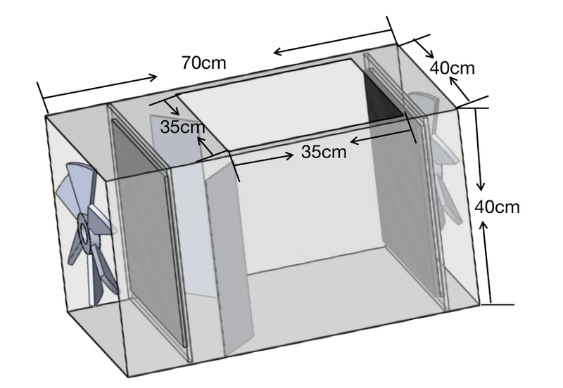
The overall design of this project could mainly be decomposed into two major boxes, one for adsorption and the other for desorption. In view of the customer requirement which requires a size limitation of 2 m3, we set size of the adsorption box to be 0.4 m × 0.4 m × 0.7 m, and the desorption box to be 0.4 m × 0.4 m × 0.4 m. For the size of the honeycomb, we design it to be 27.75 cm × 29.01 cm × 0.0.75 cm, so as to enlarge the surface area of the entire honeycomb as much as possible, while also lowering the manufacture cost to the greatest extent.
The energy consumption of our prototype will be 550 W, which is larger than our target value. The mainly effect factor of the exceeding is the desorption temperature which is at least 345 K. To meet this temperature in our desorption environment, our heating method need to consume more energy than expected. However, the desorption process needn't last a long time each day, which is around one and a half hour, we don't actually consume that much energy. The regular energy consumption will be the adsorption process which will be 180 W, which is under the target value, so the total energy consumption is acceptable.
The CO2 adsorption capacity of our prototype is 4969 mg per hour, and the prototype is expected to work four hours each day, which exceeds the initial target which is 100 mg per day.
The adsorbent regenerating temperature of our adsorbent is around 900 K, and the optimal adsorption temperature is around 298 K, which meets our target.
For the material selection, we chose to use acrylic board for the manufacture of both the adsorption and desorption boxes due to acrylic's cost-effective property. Head cover of the birdcage structure, which is served to realize the completely airtight environment for the desorption process, is made in acrylic as well. Bottom tray of the birdcage structure is made from the aluminum board, considering aluminum's relatively low density and reasonable price. The honeycomb structure is realized through 3D painting, using the PLA plastic material.
Reaction Analysis
In our entire system, the most important equilibrium reaction is the interaction of primary and secondary amines in PEI, whose monomer is C2H5N, with carbon dioxide to form carbamates, and their reaction equations are as follows:
\begin{equation}
CO_2+2RNH_2 \longleftrightarrow RNHCO_2^{-}+RNH_3^{+}
\end{equation}
\begin{equation}
CO_2+2R_1R_2NH \longleftrightarrow R_1R_2NCO_2^{-}+R_1R_2NH_2^{+}
\end{equation}
Two points are considered most important in the feasibility of such a kind of solid adsorbent being applied to our design. First is the theoretically calculation of the capacity. Following is our calculation process.
\begin{equation}
\begin{split}
M=1800~g/mol\\
Density_(PEI)=1.03~g/ml \\
Concentration=99.8%
\\
Assume\quad 2~g\quad silica\\
V_(min-PEI) = 260~m^{2}g\times2~ g\times0.2\times10^{-9}=1.04\times10^{-7} \\
m_(min-PEI)= V_PEI\times Density_PEI=0.10712~g\\
min_(rate)=\frac{0.10712}{2+0.10712}=5.08%
\\
V_(max-PEI) = 260~m^{2}g\times2 g\times0.5\times10^{-9}=2.6\times10^{-7} \\
m_(max-PEI)= V_PEI\times Density_PEI=0.2678~g\\
max_(rate)=\frac{0.2678}{2+0.2678}=11.81%
\end{split}
\end{equation}
In this calculation, we assumed a single layer load that completely covers the pore surface and estimated the approximate range of load rate.
Another one is the feasibility research of similar design for PEI using in direct air capture. For the adsorption stage, we have the equilibrium constant for kinetics and heat transfer for thermodynamics:
\begin{equation}
K_(CO_2,ads)=2.21\times10^{-5}~s^{-1}
\end{equation}
\begin{equation}
q_(eq,CO_2,ads)=1.55\times10^{0}~mol\cdot kg^{-1}
\end{equation}
\begin{equation}
K_(CO_2,des)=1.06\times10^{0}~s^{-1}
\end{equation}
\par The adsorption condition is the room temperature of 27 degree Celsius and the desorption condition is 50 degree Celsius.
Flow Analysis
In our unit, the fan blows gas into the carbon dioxide adsorption unit. The air flow speed of the fan is 0.4 m3/s.
\begin{equation}
Q=A\times v
\end{equation}
\par Q is the air flow, A is the inflow area of the carbon dioxide adsorption unit. v is the speed of the fan. The inflow length and width of the adsorption unit are 0.4 m and 0.3 m. Then
\begin{equation}
v=\frac{Q}{A}=3.33~m/s
\end{equation}
The air speed of the fan is 3.33 meter per second.
The air flow of the honeycomb is
\begin{equation}
Q=v\times Area~of~honeycomb= 0.267~m^{3}/s
\end{equation}

Deformation Analysis
Then we do the deformation analysis of the carbon dioxide adsorption box.
For the adsorption box, fix it on the both side surface. Assume the normal force on the floor surface is 30 N which is the gravity of the honeycomb and bird cage structure.
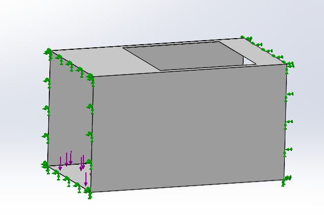
The deformation of the adsorption box is within the tolerance range.


Vacuum Test
In the process of carbon dioxide desorption, the vacuum degree test is required. We use the digital display vacuum gauge to test the vacuum degree of the carbon dioxide regeneration box.
Vacuum degree = absolute pressure - location pressure
However, due to the limited budget, we do not have enough money to buy a high-power vacuum pump, so we can not carry out a more accurate vacuum test.
Final Design
Overall Structure Design
The overall structure of this DAC device could be broken down into three parts: the adsorption box, the regeneration box, and the birdcage structure holding the adsorbents attached honeycomb. Details of the major components in this design will be illustrated as follows.
1. Honeycomb piece.
The honeycomb pieces are the objects where adsorbents are applied to.
2. Birdcage structure.
The birdcage structure is the container where honeycombs are accommodated.
Detailed dimensions of each elements are illustrated in the figure as below.

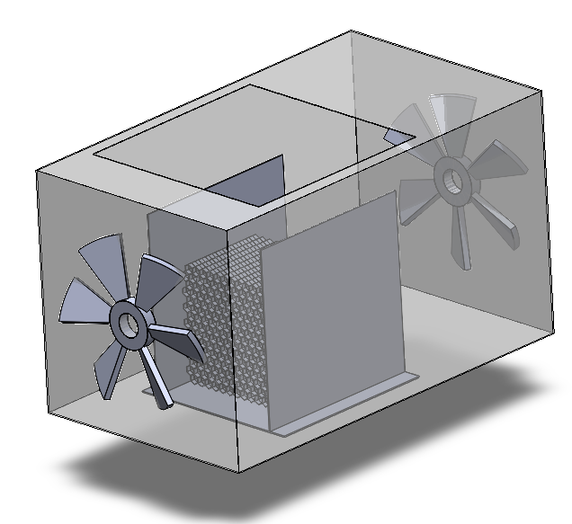
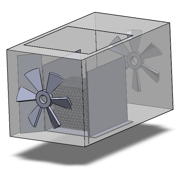
3. Adsorption box.
The adsorption box is the place where the adsorption process is conducted.
4. Filter.
Two filter pieces are placed on both ends of the adsorption box, aiming to keep away small detritus in the air.
5. Funnel.
Two funnels are set on the inlet side of the adsorption box, serving as a guiding passway for the air blown in.
6. Fan.
Two fans are utilized to inhale air into the device smoothly.
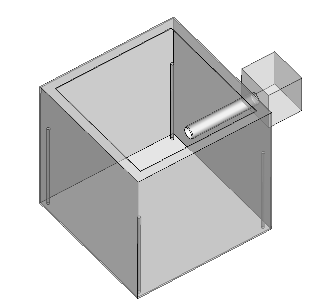
7. Desorption box.
The desorption box is the place where the desorption process is fulfilled.
8. Heating bands.
Heating bands are utilized to conduct heating during the desorption process.
9. Vacuum pump.
Vacuum pump is used for vacuumization while desorbing.
10. Spherical valve.
The spherical valve is deployed to control the flow of towards both vacuum pump and to carbon dioxide collecting container.

While operating, for the adsorption process, the birdcage structure together with the honeycomb is placed into the adsorption box through the window on the top of the box. Two fans on both ends are turned on, thus blowing air into the device. Adsorbents attached on the honeycomb will interact and fulfill the adsorption of carbon dioxide. Two pieces of filters on each end are deployed so as to keep away small gravels. While the funnel structure plays the role as a guiding passage of the air blown in. With the existence of the funnel, we could ensure that all air inhaled in by the fans could pass through the honeycomb structure, thus elavating the adsorption efficiency.

After a period of operating time, the adsorption process comes to an end. Users take out the birdcage structure manually and place it into the second desorption box. Both the vacuum pump and the heating bands are turned on in order to assist the regeneration of carbon dioxide from the adsorbents. The released carbon dioxide will be sealed inside the box and waited for further processing.

Preparation and shaping of carbon dioxide adsorbents
For the preparation of adsorbents, we use the simplest wet impregnation method for preparation. According to the calculation in 5.1.2, assuming that a single layer fully covers the pores of silica, the load ratio of PEI ranges from 5.08% to 11.81%. In the actual situation, there must be the multi-layer load, and in order to facilitate the allocation of reagents, the drug is taken according to the PEI load rate of 50.74%, and is blended with methanol into 17% PEI /methanol solution \cite{12}, and then mixed with silica. After stirring for half an hour, spin steam at 60 degrees Celsius until the methanol is dried. Then dry in a vacuum oven at 60 degrees Celsius for 12 hours, remove and seal.
The coating method is used to form the adsorbents. Because of the high viscosity of the organic solution of the adsorbents, we anticipate the use of a simple coating process for molding instead of complex laminating techniques. At first, we weigh the honeycomb structure. The excessive adsorbents are soaked with a small amount of ethanol to make the slurry, which is viscous. Dip the whole hive holder into the slurry, scoop it up and dry it after a period of time. Weigh it again, and the difference is the mass of the adsorbents.
Circuit Design
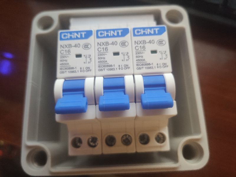
Our prototype will use four electric devices including two fans, one heating band and one vacuum pump. The vacuum pump has ground electrode while the other three haven't, so we decided to connect the other three devices into one circuit, and three switches are used to control them separately. The circuit is shown in Fig.\ref{fig:18}. If more devices are needed to be added, the circuit will look similar to the current one.
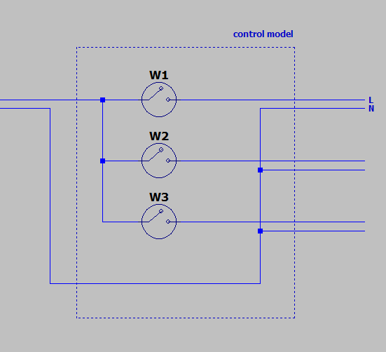
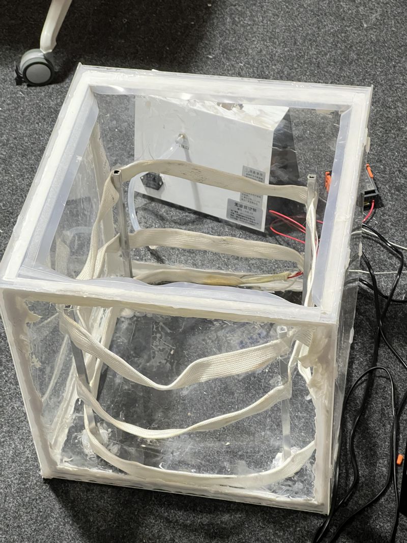
Fig.\ref{fig:19} is the completed control model put in a box. The input wire will be connected to the top of the box and the three output wires will be connected to the bottom of the box.
Validation Method
One important target in this project is to achieve at least 100 mg of carbon dioxide adsorption from the air per day, so the test of adsorption capacity is the core of this project.
The chemisorbed instrument is used to evaluate the capacity and adsorption strength of adsorbed particles on the surface of materials. Under the same conditions, the peak area is proportional to the amount of gas entering the detector, so the adsorption capacity can be detected. We use pulse injection of carbon dioxide, that is, each time the carbon dioxide content into the detector is fixed, and the peak area of this part of the carbon dioxide is also fixed, then the reduced peak area is the peak area corresponding to the adsorbed carbon dioxide. In the process of detection, helium is continuously purged as a carrier gas to provide an inert environment for detection. The fixed volume of carbon dioxide is stored in the quantization ring, at the beginning of each pulse, the valve of the quantization ring is opened, the carrier gas will flush the carbon dioxide into the detector, which is then adsorbed by adsorbents, so the carbon dioxide signal disappears. In the process of adsorption gradually reaching saturation, excess carbon dioxide is no longer adsorbed, and the peak area of carbon dioxide gradually becomes larger. When the adsorption reaches equilibrium, the peak area becomes a fixed value. For the capacity of the equipment itself, the air volume per unit time through the adsorption structure is calculated according to the flow simulation, and then the capacity can be calculated by the concentration of carbon dioxide in the air.
Another important indicator is the service life of the adsorbents, that is, the cycle period. Temperature programmed desorption (TPD) is used to detect desorption behavior by heating the material in an inert atmosphere and recording the spectrum of the removed gas by quadrupole mass spectrometry. That is, CO2 is no longer pulsed into the detector. At this time, the external carbon dioxide is no longer transported, and the carbon dioxide peak signal at this time is all from the desorption behavior. When the CO2 peak area does not increase, it indicates that desorption is complete. After desorption is complete, the above steps are repeated to test the adsorption behavior of the material again. After repeated several times, compare the reduction of material efficiency.
These are laboratory based tests. At the model level, we have a carbon dioxide detector. Due to cost and model volume limitations, the detector has a range of only 5000 ppm, which can only qualitatively demonstrate the desorption behavior of CO2. We design a three-way valve at the inlet of the vacuum pump to collect desorbed carbon dioxide and can be passed through the chromatography for content detection.
For appearance, we will evaluate the size of the adsorption box and desorption box, as well as the degree of appearance modification of the box. In addition, we have designed a logo, which is displayed in the appendix, to demonstrate our concept. For the cost, we will provide a total bill, at the same time, according to the capacity of CO2 adsorbent, saturation time, desorption temperature and cycling degree, we will estimate the daily consumption of electricity and medicine, as an indicator to detect the cost.
Ideal Design
Due to time and budget limitations, some ideal designs are abandoned. The ideal designs and improvements are listed for reference.
Mechanical arm: A mechanical arm is expected to be designed to lift the container of the honeycomb structure and swap the container between adsorbing unit and desorption unit, as well as replacing the honeycomb structure, so that the prototype is more automatic and needs less manpower.
Pressure swing adsorption method: The ideal adsorption method is to use only pressure swing adsorption method since the adsorption period is short and the energy consumption is lower. However, pressure swing is difficult to realize in daily environment, the decision matrix of deciding the adsorption method also mention this problem.
Integration of the prototype: The prototype is expected to be integrated with both adsorption and desorption functions, while the current design is separated into two parts. The reason is the air tightness of the integrated prototype is hard to guarantee with three openings on three sides, which will cause difficulties collecting CO2 after desorption.
-
Validation
Validation Results
Capacity
For the test of adsorption capacity, we design the following experimental conditions: no pretreatment, room temperature, the filling load of 100 mg, He with a flow rate of 20 sccm is used as the carrier gas, and CO2 with a flow rate of 50 sccm is used as the reaction gas, pulse injection. No pretreatment is to prevent the pyrolysis of PEI, and room temperature is the most DAC friendly temperature. The concentration of CO2 is much higher than the proportion of CO2 in the air, which is to shorten the time required to reach adsorption equilibrium and facilitate the test. The CO2 peak area of pure gas and with adsorbents is tested by chemisorbed instrument until the adsorption reached equilibrium, which means, the peak area is no longer reduced, and the sampling is stopped. The total area reduced is the adsorbed CO2 capacity.
Before this, we tried continuous sampling test. The experimental conditions were 5% CO2 and 95% N2, with helium as carrier gas. Measured every seven minutes, the peak area of carbon dioxide is shown in Table.\ref{conti}. It can be seen that there is almost no reduction in the peak area of carbon dioxide, and the possible reasons are: First, we use improper sealing. The number of samples are too small and air contact time is too long, leading to saturation, and it is difficult to solve it by pretreatment due to PEI pyrolysis. Second, due to continuous sampling, the chromatogram is saturated before it reaches stability to begin testing. Third, the CO2 peak area is small for chromatography, because the chromatographic signal is much less pronounced, and it is difficult to judge whether the variation is an error. According to this, we further design the temperature programmed desorption experiment to test the desorption performance of the adsorbents, so as to determine whether it is due to saturation.

The following are the results of the chemisorbent pulse adsorption test for the first time of adsorption, as shown in Table.\ref{pulse1}. The pulse time is 120 s and the interval time is 120 s. The volume of one pulse is 0.47 ml. As can be seen from Fig.\ref{fig:26}, the first adsorption cycle ends within 40 minutes. The first four frames of carbon dioxide are completely adsorbed, while from the tenth frame, the area of carbon dioxide hardly increases. Therefore, based on the average value of 9-13 frames, the peak area of a frame of pure carbon dioxide can be calculated to be approximately:
\begin{equation}
A_{pure CO2} = \frac{25434.35+25454.2+25380.55+25442.65+25415.7}{5} = 25425.9
\end{equation}
Then the adsorbed carbon dioxide corresponds to the missing peak area of the first eighth frames:
\begin{equation*}
A_{loss} = 25425.9 \times 8 - 22042.651 - 22494.65 - 23643.551 - 24408.4 - 24605.2
\end{equation*}
\begin{equation}
= 86212.748
\end{equation}
Because the peak area is proportional to the gas content, and the volume of CO2 in a frame is 0.47 ml, then the adsorption capacity of 100 mg PEI/silica is:
\begin{equation}
V_{capacity} = \frac{0.47 \quad ml \times 86212.748}{25425.9} = 1.594 \quad ml
\end{equation}
\begin{equation}
m_{capacity} = 0.001594 \quad L \times 1.997 \quad g/L = 3.183 \quad mg
\end{equation}
\begin{equation}
Capacity = \frac{3.183 \quad mg} {44 \quad g/mol \times 0.1 \quad g} = 0.723 \quad mmol/g
\end{equation}
This catalyst has reached the adsorption level of normal solid catalysts. One epoxy-butane modified PEI/silica carbon dioxide adsorbent can reach 1.5 mmol/g \cite{12}. The capacity range of PEI/silica adsorbents available on the market is about 0.417 - 4.458 mmol/g, without considering other factors such as adsorption efficiency, cycle period, preparation cost, etc.
For the shaping of the adsorbents, due to the limitations of technology and cost, we choose the simplest coating. The coating effect is shown in Fig.\ref{fig:27}. The viscosity of the organic solution of the adsorbents is not as good as expected, resulting in certain problems in the uniformity of the coating, the loading mass, and the degree of adhesion between the powder and the scaffold. Even if the buffer section and dust diaphragm are added in the middle of the fan and support, there is still a certain loss rate in the actual test, and the loss rate increases with the use of time. This defect can be solved by timely replenishment of the adsorbents, because ethanol, which is easily dried, is used as the dissolving agent. Therefore, in the calculation of capacity, this defect is ignored, while it is taken into account in the life cycle estimation.
According to the quality difference before and after coating, the quality of the adsorbents coated on the single honeycomb scaffold is:
\begin{equation}
Mass_{single} = 84.79 \quad g - 76.98 \quad g = 7.81 \quad g
\end{equation}
Assuming that all honeycomb load masses are uniform, the total load mass of the catalyst is:
\begin{equation}
Mass_{total} = 7.81 \quad g \times 20 = 156.2 \quad g
\end{equation}
That is to say, after ignoring the differences between the honeycomb scaffolds and the batch of adsorbents errors, the theoretical capacity of the model is:
\begin{equation}
Capacity_{total} = 0.723 \quad mmol/g \times 156.2 \quad g = 112.93 \quad mmol
\end{equation}
According to the following test, this adsorbent can be recycled at least 4 times a day, then the mass of carbon dioxide adsorbed in a day is at least:
\begin{equation}
Capacity_{day} = 0.11293 \quad mol \times 44 \quad g/mol \times 4 = 19.876 \quad g = 19876 \quad mg
\end{equation}
This is well above our target of 100 mg/d.
Saturation time
Because the concentration of CO2 in the air is 0.04%, according to the flow simulation in 5.1.3, the amount of air passing through the adsorption scaffold per second is 0.267 × 10⁶ ml, then the volume of carbon dioxide passing through the adsorption scaffold per second is:
\begin{equation}
0.267 \times 10^{6} \quad ml/s \times 0.04\% = 106.8 \quad ml/s
\end{equation}
Therefore, time required for adsorption saturation is:
\begin{equation}
time = \frac{0.11293 \quad mol \times 44 \quad g/mol}{1.997 \quad g/L \times 106.8 \times 10^{-3} \quad L/s} = 23.298 \quad s
\end{equation}
In other words, for a device equipped with 156.2 g adsorbents, the first adsorption saturation time takes about 23.298 s, and it can adsorb CO2 of 112.93 mmol. In the later tests, the saturation time of the three adsorption cycles does not change much.
Cycle period
Then I conduct a temperature programmed desorption experiment at 80 degrees Celsius, and the CO2 is completely desorbed within 10 minutes. Then I repeat the adsorption-desorption cycle for three times, and the adsorption capacity of carbon dioxide is respectively 0.721 mmol/g, 0.703 mmol/g, and 0.702 mmol/g. And the loss rates are respectively 0.277%, 2.766%, and 2.905%. Therefore, the adsorption capacity of this adsorbents remains almost constant during the three cycle periods.
Total time
The first adsorption saturation time is 23.298 s. Time to change the position of the bracket is negligible, and the time to calculate is for the heating belt to raise the temperature to the temperature required for desorption, that is, 80 degrees Celsius. In the actual test, we use an insulating diaphragm to improve the heating efficiency of the heating belt. To further reduce the time to reach the temperature required for desorption, set the maximum temperature of the heating belt, which is 150 degrees Celsius. At this time, the temperature of the support is tested with a probe thermometer, and the time to reach 80 degrees Celsius is 15 min. The desorption time is 10 min, and after 10 min, the temperature of the stent is about 90 degrees Celsius. The stable temperature of PEI for a long time is about 160-200 degrees Celsius, so it is feasible. The preheating and adsorption of the desorption chamber can be carried out simultaneously, so the first cycle takes:
\begin{equation}
t_1 = 15 \quad min + 10 \quad min = 25 \quad min
\end{equation}
For the second cycle, the first cooling takes 10 min. At this time, the temperature of the heating belt needs to be adjusted in real time to prevent PEI pyrolysis caused by excessive temperature. The desorption time is still 10 min, so the time of the second cycle is:
\begin{equation}
t_2 = 10 \quad min + 10 \quad min = 20 \quad min
\end{equation}
Assuming that a batch of adsorbents is cycled for 4 times, without taking into account additional time such as intermediate replacement of adsorbents, the total time is:
\begin{equation}
t = 25\quad min + 20 \quad min \times 3 = 85 \quad min
\end{equation}
Life cycle assessment of DAC
We should do the life cycle assessment of DAC we design for the industry to know the energy consumption and emission of carbon dioxide. In the life cycle assessment, we divide it into five life stages, raw material stage, manufacture stage, transportation stage, use stage and end-of-life stage. Ignore the manufacture stage because the carbon dioxide emission is small. We ignore the carbon dioxide emissions of manufacturing PEI-Silica because we can reuse it. Because the DAC machine can work for many years, we don't consider the end of life stage. We research other people's life cycle assessment articles and give our own assumptions to do the life cycle assessment for the DAC machine. For the raw material stage, the carbon dioxide emissions for 1 kg PLA plastic is 0.5 kg \cite{9}. The carbon dioxide emissions for 1 kg aluminum alloy is 0.23917 kg and the electricity power costs is 213 kJ \cite{10}. We assume using truck to transport 10000 kg raw materials for 100 km. The carbon dioxide emission is 84.5 kg per 100 $km$. For the use stage, the fan's power is 350 W and the vacuum power is 550 W. Based on electricity grid of China, it releases 0.7694 kg CO2 per kwh \cite{11}.

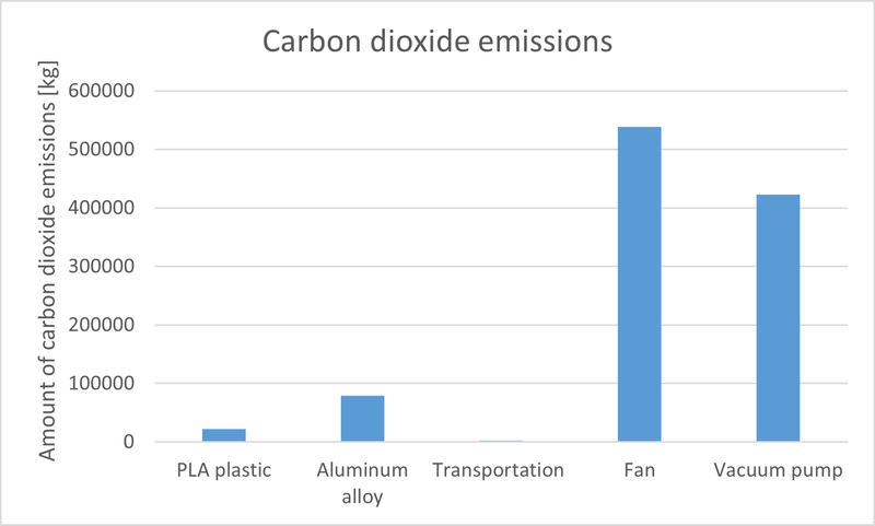
In our own experiment, 165 g PEI-Silica can adsorb 4.969 g of carbon dioxide. Assume we use 0.5 kg PEI-Silica for one DAC unit. Assume the time for adsorption is 10 min and the time for regenerating carbon dioxide is 5 min. We need 1 fan and 1 vacuum pump for 10 DAC units to adsorb carbon dioxide and regenerate carbon dioxide. Then for 30000 DAC machines working 1000 hours, the CO2 emissions are 1.0656 × 10⁵ kg, the adsorption of CO2 are 1.8069 × 10⁶ kg. Net adsorption of carbon dioxide is 7.4130 × 10⁵ kg. This is a very rough estimate, but it is enough to prove that our product can adsorb carbon dioxide in industry. If we use more clean energy to power the fan and vacuum pump, the net adsorption of carbon dioxide can be large.
-
Modeling and Analysis
Manufacturing Plan
This section describes the material, approach and budget for our own design and industrial mass production of DAC.
Manufacture and Assembly Process
This section describes the material, approach and budget for our own design.
1. Birdcage structure with honeycomb.
This birdcage structure with honeycomb represents the core component of this device. First of all, Aluminum boards are purchased and being machined into required size. Next, two side boards are fixed to the bottom board with screws and nuts. On this stage, the bottom tray of the cage has been completed. Then, the Acrylic boards are processed into correct dimension through laser cutting. Gluing the four side Acrylic boards with the bottom board, the top cap of the cage is finished. After that, we drill several holes on each side board of the top cap, as well as on side boards of the bottom tray. Threading ropes through these side holes, connection between the cap and tray could be realized.
The honeycomb structure serves as the supporter for the adsorbents in this design. To manufacture the entire honeycomb, 20 pieces of single-layer nests are 3D painted using PLA plastic. After applying the adsorbents to the layer pieces, we put each piece into the finished birdcage structure. The final step is to threading another rope through side holes around the honeycomb, thus ensuring that the layer pieces stay steadfast to the birdcage.


2. Adsorption box.
This structure aims for the adsorption process of carbon dioxide. Acrylic boards are purchased and undergo laser cutting into required size. We glued four side boards together and fixed two fans to both ends of the tunnel using screws and nuts. These two fans ensure the smooth flow getting through the box. A square-sized window and two small gaps close to each end are hollowed out with laser cutting on the top board of the box. This window is for the freely moving in and out of the birdcage structure, while the two gaps are for the pulling in and out of filter pieces. Again we deployed laser cutting to cut Acrylic boards into required size, gluing two funnel boards to the gap between the side walls of the adsorption box and the aluminum side boards of the birdcage structure. Two pieces of filter sponges are cut into required size with scissors, gluing to the prepared Acrylic boards with a large center square hollowed out. Placing the filter boards into the adsorption box through two gaps on the top of the box, the adsorption box is completely accomplished.

3. Desorption box.
This structure is for the regeneration process of carbon dioxide. Similar with the manufacture of the adsorption box, Acrylic boards are cut into required size and glued together. In addition, a side hole is required on one side of the box, which is where the vacuum pump could be connected to. Four Aluminum sticks are glued to the bottom of the box so that the heating bands could be wrapped on. In addition, for appearance optimization, we printed our team logo as well as emblem of the institute, pasting them on outside side walls of the box.
Component Materials and Manufacturing Process
This part describes the materials and production methods needed for industrial mass production.
1. Honeycomb: Use the injection modeling process to make the honeycomb structure. The material we use is PLA plastic. We need 1.5 kg PLA plastic for each unit.
2. Adsorption and regeneration box: The material we use for the box is aluminum alloy sheet. Buy the aluminum alloy plate from the aluminum manufacturer for cutting, and use the laser cutting machine to cut the aluminum alloy plate into an appropriate shape. Drill holes in the aluminum plate and screw in to secure it. The thickness of the sheet is 2 mm. The area of the sheet is 2 m2.
3. Fan: Buy the fan from the fan manufacturer, the size of the fan is 0.4 × 0.4 m2. We need a fan for 10 units.
4. Dust sponge: Buy the dust sponge from the sponge manufacturer, the area of the dust sponge is 0.32 m2 and the thickness is 2 mm.
5. Bird cage: The material we use for the bird cage is aluminum alloy sheet. Buy the aluminum alloy plate from the manufacturer for cutting, and use the laser cutting machine to cut the aluminum alloy plate into an appropriate shape. Drill holes in the aluminum plate and screw in to secure it. The thickness of the sheet is 2 mm. The area of the sheet is 0.225 m2.
6. Vacuum pump: In the industry, we use vacuum pump to vacuumize the regeneration box to let the carbon dioxide desorption. We buy the vacuum pump from the vacuum pump manufacturer. We use 1 vacuum pump for 10 units.
7. Adsorbent: In the industry, both PEI and silica are very common can easy to get by purchasing from chemical reagent company with various models and specifications.
Important Tolerances
A laser cutting machine is used in the cutting of aluminum alloy plates, and the tolerance of the laser cutting machine is smaller than 0.4 mm which is allowed in the manufacturing process.
Machine and labor
The price of the laser cutting machine which can cut the metal is about 20 thousand CNY. We assume the labor cost of one unit is 500 CNY.
Budget Consideration
Here is the table of the budget consideration of one unit.
In the industrial mass production, assuming the need for forty laser cutting machines, and the cost is 800 thousand CNY. Assume we produce 30000 units of DAC, ignore the electric charge, the money we need is 5.0627 × 10⁷ CNY. For each DAC machine produced, we need about 1688 CNY.
-
Conclusion
Engineering Changes Notice
Sealing strip
We stick the sealing strip on the opening part of the regeneration box. We place the plastic seals on the four sides of the opening. So that when we put the bird cage structure in the middle of the regeneration box, there will be no air leakage, which improves the air tightness when carbon dioxide is desorbed.
Filter screen
We designed a new structure, which installed a layer of filter sponge behind the fan to filter dust in the air and increase the efficiency of carbon dioxide adsorption.
To make the air flow faster, we added another fan to the back of the adsorption box. When carbon dioxide adsorption is carried out, the front and rear two fans rotate together, the front fan blows wind in the device, the rear fan quickly exports the adsorbed air, increasing the carbon dioxide adsorption efficiency.


Windshield
To make better use of air entering the adsorption box, we added two windshields at the air intake inlet (behind the front fan), forming a funnel shape so that the air entering the unit only passes through the honeycomb structure, increasing the efficiency of carbon dioxide adsorption.
We put the ECN engineering drawing in the appendix ECN part.
Project Timeline
Project timeline is shown in Fig. \ref{fig:20}:

Our overall process keeps up with the plan. Although we meet some challenges during the process, responsible solutions and adjustments are applied to reach the target. The prototype is assembled and beautified, while the performance is also convincing and satisfied.
Discussion
After all of the whole prototype, this demo has been designed to adsorb carbon dioxide by direct air capture processing. Obviously, this demo has some advantages and disadvantages. Based on morphological analysis, we make choices that are relatively appropriate for our situation. These include time constraints, financial constraints, site constraints, equipment constraints, and so on. These can all be optimized in a series of facts. The most prominent advantage is that this prototype is a relatively early project in the country, which may provide effective guidance for a series of subsequent studies. The drawbacks mainly lie in the fact that this relatively crude demo has some issues, including the small size, which is not exactly the same for guiding production. At the same time, low intelligence and automation, which is not completely consistent with the original intention of our design of this product leave it alone.
Of course, in the course of the preceding series we encounter a series of oversights just as in the morphological analysis we make a series of improvements and choices. Some of the problems we encountered, both large and small, included that, considering that leaving only one side of the intake would cause turbulence in the adsorption chamber, we decided on a double-sided opening to guide the forward flow of the air. Considering that air is a mixture of impurities widely distributed, we consider the need to use some dust sponge to block some fine dust, and this sponge can also do a role of guiding the air flow. The second point is that in the process of desorption, the TPSA method has been mentioned above, that is, we tend to form a relatively vacuum or less negative pressure chamber. Therefore, in addition to the conventional silicone sealing of the gap, we used rubber rings to further seal our design. Third, in order to build the whole prototype, we use a variety of materials such as polymer, aluminum alloy, iron, etc. Various shaping techniques are needed to integrate these different materials. Due to the limitation of instruments, we cannot successfully weld aluminum alloy and iron plate together, so we choose to connect them with Angle iron. Fourthly, one of the difficulties is that our PEI-silica needs to be modified to a certain extent in order to significantly improve the adsorption efficiency. The adsorption efficiency of PEI without modification or modification is not high enough. But it still met our design needs. However, this modification is still a point worth further improvement. Finally, a similar issue, we used 3D printing to build the perfect base attached honeycomb design, however due to the size limitations of the printer, we had to scale down our design to ensure the success of the print. With the reduction of our load, we use binder to stack multiple structures to increase the load rate and increase the adsorption contact area.
Conclusion
This project aims to address the urgent need for carbon dioxide reduction and contribute to the global efforts in combating climate change. The small device designed by our team utilizes solid amine adsorbent technology, which has shown promising results in capturing more than 100 mg of carbon dioxide per day directly from the air. One of the key features of our project is the use of adsorbents to efficiently capture carbon dioxide and then utilize heat in the carbon dioxide regeneration box for desorption and reuse. This innovative approach not only ensures effective removal of carbon dioxide but also promotes sustainability by minimizing energy consumption. To further enhance the efficiency of our device, we have incorporated a honeycomb design that significantly increases the reaction area between carbon dioxide and adsorbents. By maximizing contact between these two elements, we can achieve higher levels of adsorption efficiency, making our device even more effective at capturing carbon dioxide from ambient air. In selecting solid amine adsorbents as our primary material, we have considered equilibrium thermodynamics principles and available data sets to estimate its potential capacity. While direct air capture (DAC) holds great promise as an important means towards achieving carbon neutrality due to its location flexibility and negative emission ability, it is still in its early stages with start-up companies and prototypes dominating the field.
Therefore, this project seeks to provide valuable reference value and experimental data that can support large-scale expansion of DAC applications. By conducting thorough research on various aspects such as performance optimization, cost-effectiveness analysis, and environmental impact assessment, we aim to contribute towards establishing DAC as a viable solution for reducing atmospheric CO2 levels on a global scale.
Future Works
In our design, we have implemented a basic demo of a contactor that adsorbs carbon dioxide directly from the air. For further study of our design that future generations may be exposed to, there are some directions or points of design that can be provided. The first is the overall intelligence study of our prototype, which includes the addition of a robotic arm to help us design a honeycomb device that is free of manual manipulation to move and adsorb. At the same time, the automation of other parts of the circuit and electrical components can also be considered as a direction. In addition, possible subsequent improvement plans include changing the types of adsorbents used to increase capacity. At the same time, the overall structure is optimized, including better setting the overall structure layout and other directions. Finally, in addition to making improvements on our basis, a redesign to optimize the overall structure is also a very good idea. Due to various conditions, this prototype uses two chambers to achieve adsorption or desorption, which can be studied in one chamber in the original design, which includes some of the exploration of ways to achieve higher vacuum.
-
Acknowledgement
This project is sponsored by Professor Yulian He from UM-SJTU Joint Institute, who is also the instructor of this project. Here we want to express our thanks to Professor Yulian He, Jigang Wu, Chengbin Ma, and Chong Han for their valuable instruction on the technique and presentation of this project. Special thanks for Professor Mingjian Li and assisstant management Haichuan Wang who helped for laser cutting, and Dr.Liuqingqing Yang and Dr.Feixiang Tian who provided guidance for the Chromatographic detection.
-
Reference
[1] L. S. W. R. J. Q. Z. Y. Z. Q. . . . P. S. Gao, W., “Industrial carbon dioxide capture and utilization: State of the art and future challenges,” Chemical Society Reviews, vol. 49, no. 23, pp. 8584–8686, 2020.
[2] L. W. X. Zu., S. Wang., “Life cycle analysis of greenhouse gas emissions of china’s power generation on spatial and temporal scale,” Energy science engineering, no. 10, pp. 1083–1095, 2022.
[3] B. D. B. . Sapp, M. (2021). IEA reports compares different pathways for CCUS. Biofuels Digest [BLOG].
[4] Z. H. . G. P. Lackner, K., “Carbon dioxide extraction from air: Is it an option?” 1999.
[5] K. Lackner, “The thermodynamics of direct air capture of carbon dioxide,” Energy (Oxford), vol. 50, pp. 38–46, 2013.
[6] H. G. S. A. D. . H. K. Keith, D., “A process for capturing co2 from the atmosphere,” Joule, vol. 2, no. 8, pp. 1573–1594, 2022.
[7] D. S. A. K. H. David W. Keith, Geoffrey Holmes, “A process of capturing CO2 from atmosphere,” Keith et al., Joule, vol. 2, pp. 1–22, 2018.
[8] Z. C. D. M. R. G. A. M. Maria Erans, Eloy S. Sanz-Peroz,Dawid P. Hanak, “Direct air capture: Process technology, techno-economic and socio-political challenges,” Energy Environ. Sci., vol. 15, no. 1360, pp. 1360–1405, 2022.
[9] G.G.-J.R.Schleussner, Carl-FriedrichandM.J.Gidden, “Anemissionpath way classification reflecting the paris agreement climate objectives.” Communications Earth Environment 3, no. 1, pp. 1–11, 2022.