Student Projects
Lens-based beam-forming antenna by micro-manufacturing
Project Video
Team Members

Team Members:
曾亦炜 Yiwei Zeng, 孙云聪 Yuncong Sun, 张克冰 Kebing Zhang, 李劲源 Jinyuan Li, 王烁丁 Shuoding Wang
Instructors:
Jigang Wu
Project Description
-
Problem

Chapter One Problem and Introduction
1.1 Background
In recent times, both the scientific community and the industry have directed their focus towards exploring various frequency bands to meet the growing bandwidth demands of modern communication systems. Among these bands, the millimeter-wave frequency range has emerged as a particularly intriguing option due to its vast available bandwidth[1]. However, it is crucial to consider the implications of the Friis transmission formula, which reveals that free-space propagation results in significantly higher path loss at millimeter-wave frequencies compared to lower microwave frequencies. ILLUSTRATION 1-1 shows the free space path loss for different frequency waves. For instance, the path loss at 50 GHz exceeds that at 2.45 GHz by 30 dB at d = 0.02 km[2] . Consequently, the implementation of millimeter-wave systems introduces a unique set of stringent requirements, especially from the perspective of antenna design and performance.

ILLUSTRATION 1-1 Free Space Path Loss for Different Frequency Waves[2]
1.2 The Significance of Thesis Work
The conventional approaches in antenna design have primarily relied on printed technology, particularly patch arrays, which can achieve high gains but necessitate intricate and costly feeding networks. Moreover, they are susceptible to losses caused by dielectric and conductive factors[3]. Consequently, lens antennas have emerged as promising alternatives in such scenarios. The advantage of lens antennas lies in their ability to obviate the need for expensive and complex feeding networks which are hard to implement at targeted frequencies. However, the drawback is that their manufacturing poses difficulties, given their intricate geometries and the need for specific refractive index materials.
In recent years, 3D-printing has emerged as a notable technology for implementing high-frequency structures[4]. The introduction of low-loss dielectric and conductive filaments, coupled with the advancements in the new generation of 3D-printers encompassing lower costs and enhanced precision, has facilitated the realization of various high-frequency topologies that were previously challenging or economically unfeasible to manufacture[5]. This progress paves the way for the implementation of cost-effective solutions.
In this article, 3D-printed Fresnel Zone Plate and Metamaterial Lens on 28 GHz are designed and produced, which overcome the manufacturing difficulties of lens antennas in a low cost. The design shows the possibilities of cheap and easy manufacturing lens antennas. The pursuit of these objectives holds great significance for various applications, including Low Earth Orbit (LEO) satellite networks, fifth and sixth-generation (5G, 6G) mobile communication systems, and advancements in radar and detection technology[6].
-
Concept Generation
Chapter Two Concept Generation
2.1 Literature Searching
In the concept generation phase, a systematic approach is adopted, drawing insights from the existing literature through comprehensive literature reviews. As a starting point, scholarly sources such as research papers, journal articles, and conference proceedings are diligently examined to identify potential concepts related to our project.
Within the domain of antennas, two main directions are considered, namely active and passive antennas. Active antennas, also referred to as reconfigurable antennas, offer the notable advantage of reconfigurability, enabling dynamic alteration of their characteristics to adapt to varying operational environments[7]. Consequently, reconfigurable antennas present a practical solution to circumvent the need for multiple radiating structures while simultaneously fulfilling the specified performance requirements. Nevertheless, it is important to acknowledge that reconfigurable antennas come with inherent disadvantages. The incorporation of circuit structures and the requirement for a more intricate manufacturing process pose challenges, and the need for power may impose limitations on their usability.
In contrast, passive antennas place their emphasis on the physical structure and materials utilized in their construction. A primary advantage of this direction is the inherent cost-effectiveness, ease of assembly, and simplified manufacturing processes[8]. However, it is essential to recognize that achieving comparable performance to active antennas demands a concerted effort. Besides, the reconfigurability is not available for passive antennas.
2.2 Concept Generation
During the phase of concept generation, it is imperative to thoroughly explore a diverse range of concepts to ascertain the full spectrum of possibilities. To this end, two distinct concepts are selected from each direction under consideration. Within the realm of active antennas, the transmitarray and phase shift array are identified as the chosen concepts. Conversely, in the context of passive antennas, the fresnel zone plate and metamaterial lens are singled out as the selected concepts. By comprehensively examining various possibilities from both active and passive antenna directions, we aim to broaden our understanding and make informed decisions for the subsequent stages of our project.
2.2.1 Transmitarray
Transmitarray technology utilizes independent Transmit/Receive (T/R) components and digital phase shifters for precise beamforming. They consist of an array of unit cells placed above a source antenna. Phase shifts are applied to the unit cells, between elements on the receive and transmit surfaces, to generate transmitted waves.
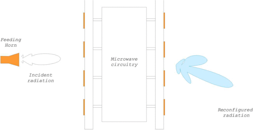
ILLUSTRATION 2-1 Fundamentals of Transmitarray[9]
The fundamentals of transmitarray lens structures can be readily comprehended. Initially, the lens' reception interface captures an electromagnetic wave characterized by specific wave-front properties. Subsequently, the received signal undergoes a distinct processing procedure, involving phase shifts, amplification, or other relevant manipulations. As a result of the modifications introduced during the processing stage, the processed signal is retransmitted, exhibiting new wave-front properties[9]. The schematic representation of this process is illustrated in ILLUSTRATION 2-1.
2.2.2 Phase Shift Array
The Phase Shift Array approach relies on Frequency Selective Surfaces (FSS) incorporating metal resonance cells.The antenna system consists of an array of radiating elements, each equipped with a phase-shifting component. The FSS, through its frequency-dependent transmission and reflection properties, allows for precise control of the phase of the radiated waves. This enables beamforming and manipulation of electromagnetic waves.
ILLUSTRATION 2-2 depicts the configuration of the active Frequency Selective Surface (FSS) unit, comprising two low-loss substrates that are positioned between three metallic sheets. Both the top and bottom sheets exhibit etched slots, endowing them with capacitance properties when subjected to x-polarized electric incidence. The middle sheet, on the other hand, is etched with a circular hole, effectively resembling a single-turn coil at its inner edge. The integration of two varactors onto the slots introduces tunability to the FSS unit, thereby enabling dynamic adjustments to its characteristics[10].
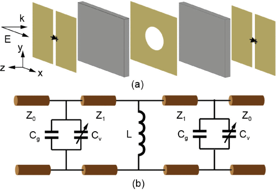
ILLUSTRATION 2-2 FSS Unit[10]
2.2.3 Fresnel Zone Plate
The Fresnel Zone Plate technique utilizes fundamental geometric principles and varying material profiles to achieve constructive interference at the focal point, akin to the behavior observed in convex lenses.
In the Fresnel Zone Plate, the structure involves the obstruction of alternating Fresnel zones using annuli composed of perfect electrical conductors (PEC), as exemplified in ILLUSTRATION 2-3. Evidently, a portion of the incident field encounters reflection by the opaque zones, while the remaining fraction transmits through the transparent zones. This division leads to constructive interference of the reflected field at a distance F in front of the zone plate, as well as constructive interference of the transmitted field at a distance F behind the zone plate. Consequently, two focal points are associated with this structure, rendering it suitable for utilization as either a transmission zone plate or a reflection zone plate, contingent upon the placement of the feed in relation to the incident wave[11].
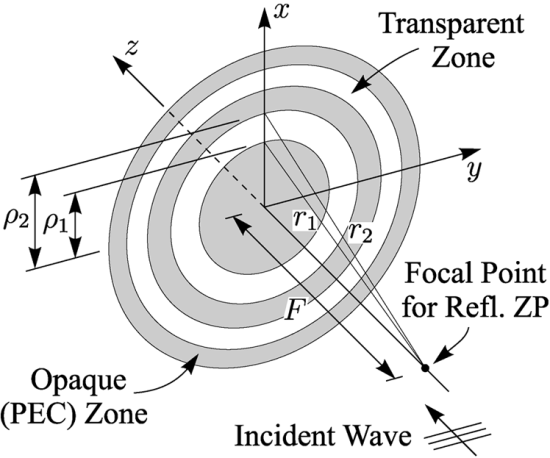
ILLUSRATION 2-3 Fresnel Zone Plate[11]
2.2.4 Metamaterial Lens
Metamaterial Lens consists of transparent rings with different permittivity values. The phase difference between these rings is carefully designed to ensure constructive interference at the focus. By manipulating the permittivity values, the lens can further enhance the signal amplification[12], as exemplified in ILLUSTRATION 2-4. The focus and phase shift calculation are similar to Fresnel Zone Plate.
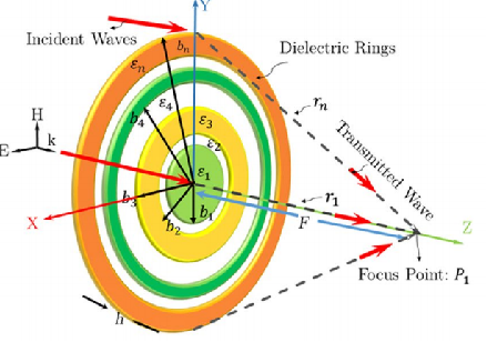
ILLUSRATION 2-3 Metamaterial Lens[12]
Because of the difficulty of fabricating lenses through the fusion of different permittivity materials, alternative methods can be used. For example, the relative permittivity of a dielectric substrate material can be reduced by perforating a single layer of substrate. If the diameter of holes and the distance between holes are kept small compared to the wavelength of operation, the substrate will appear to have a uniform effective permittivity[1].
-
Design Description
Chapter Three Parameters of Final Design
3.1 Parameters of Fresnel Zone Plate
The final design of Fresnel Zone Plate is shown in ILLUSRATION 3-1, and its dimension is shown in front view ILLUSRATION 3-2 and side view ILLUSRATION 3-3. Since the shape of Fresnel Zone Plate is circular, the top view and side view are totally the same. The inner circle has the diameter of 42.8 mm, and the outside circle has the diameter of 107.0 mm. The depth of Fresnel Zone Plate is 2.0 mm. Consider the cost and convenience, we select stainless steel as the manufacturing material of our final design.

ILLUSRATION 3-1 Master Drawing of Fresnel Zone Plate
ILLUSRATION 3-2 Front View of Fresnel Zone Plate
ILLUSRATION 3-3 Side and Top View of Fresnel Zone Plate
3.2 Parameters of Metamaterial Lens
The final design of Metamaterial Lens is shown in ILLUSRATION 3-4, and its dimension is shown in front view ILLUSRATION 3-5 and side view ILLUSRATION 3-6. Since the shape of Metamaterial Lens is circular, the top view and side view are totally the same. To prevent signal from being blocked by the center, we make it hollow to allow better transmission performance. The inner circle has the diameter of 27.8 mm, and the outside circle has the diameter of 100.2 mm. The depth of Metamaterial Lens is 14.6 mm. We select PA12 as 3D printing material to build Metamaterial Lens as it has our desired relative permittivity 3 at 28GHz.
ILLUSRATION 3-4 Master Drawing of Metamaterial Lens
ILLUSRATION 3-5 Front View of Metamaterial Lens
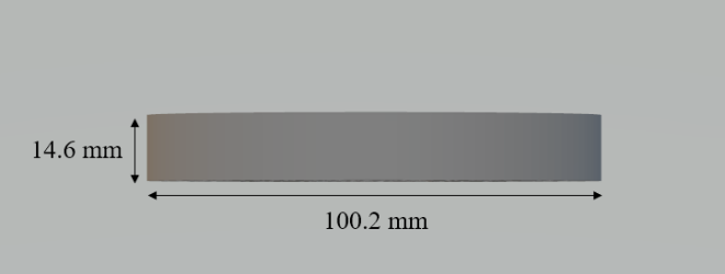
ILLUSRATION 3-6 Side and Top View of Metamaterial Lens
-
Validation
Chapter Four Valildation
4.1 Validation Plans
With the design of our products, we have already finished the engineering specifications on size, machining accuracy, material type and cost. We tested the other parameters including gain, frequency, bandwidth, scanning range in the Laboratory of Antenna and Scattering, SJTU
Before the testing, we installed the testing probe and the tested antenna, and also we connected the RF cables. We aligned the transmission-reception so that they are centered in the middle.
After the pre-test, we first recorded the signal without FZP or Metamaterial Lens. Then, we set the FZP at 45 mm away from the reception antenna, with the FZP parallel to the antenna and 10° to the antenna, respectively. Finally, we tested the Metameterial Lens at 35 mm away from the reception antenna. The antenna and the lens are rotated from -180° to 180°.
4.2 Validation Results
The final results are shown as below. ILLUSTRAION 4-1 shows the 0° case of FZP and ILLUSTRAION 4-2 shows the 10° case. The signal is concentrated at the center (θ=0°), and it has a gain about 10.1 dB while in the 10° case it has about 8.7 dB gain. This means that the FZP works better when it is parallel to the antenna, but still has rather high gain when there exists small degrees between FZP and the reception antenna. Besides, we notice that there are also several peaks at other angles. We consider this happens because at larger angles there might be scattering of electromagnetic wave by metals. The superposition of waves causes the enhancement of signal.
For the Metamaterial Lens, on the other hand, we get good concentration of signals. ILLUSTRAION 4-3 shows the 0° case of Metamaterial Lens. Compared to the reference signal, there is a peak at 0° which has around 8 dB of gain. This means the lens have successfully concentrate the signals around 0° to the center and fits our simulation very well.
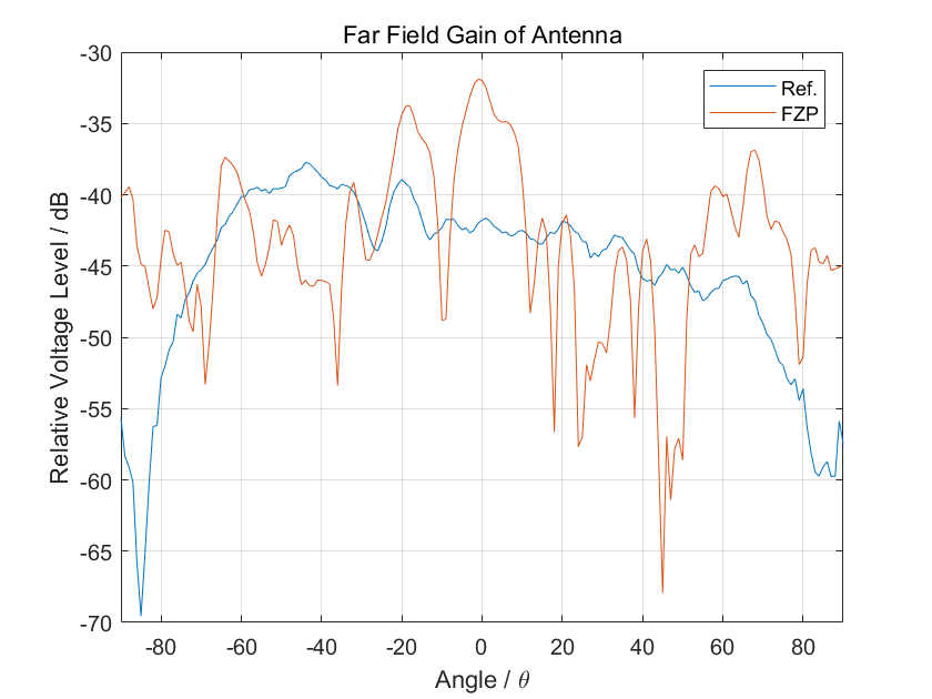
ILLUSRATION 4-1 FZP Working at 28 GHz, 0°
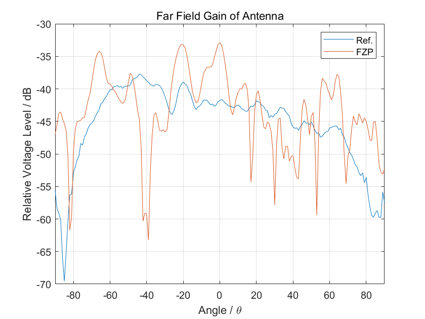
ILLUSRATION 4-2 FZP Working at 28 GHz, 10°
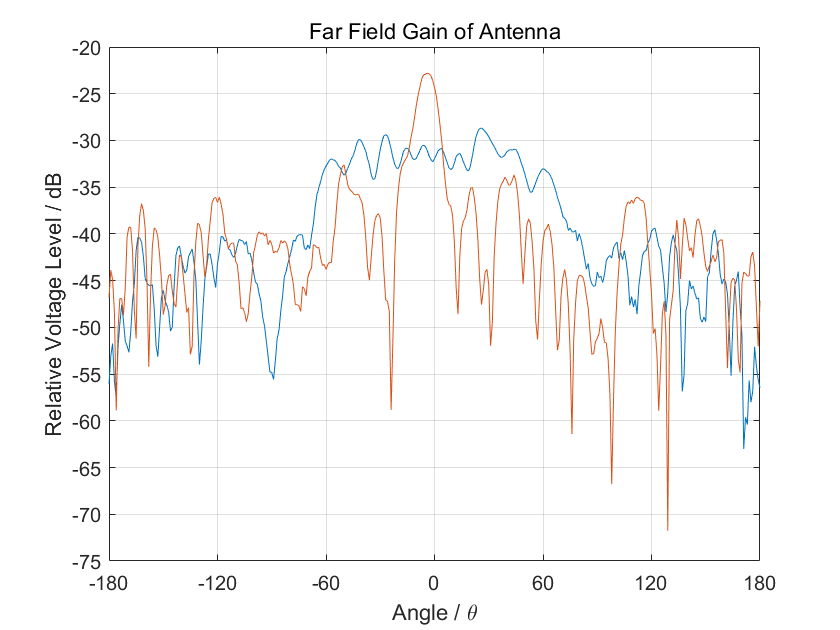
ILLUSRATION 4-3 Metamaterial Lens Working at 28 GHz, 0°
-
Modeling and Analysis
Chapter Five Modeling and Simulation
To test the performance of our designs, we first test the model in ANSYS Electromagnetics Suite 2023 R1. In the simulation, we use large air box to approximate real electromagnetic environment. If we could observe a high gain of power near the focus of our designs, then the feasibility of our designs is verified. Otherwise, modifications on designs will be made.
5.1 Simulation of Fresnel Zone Plate
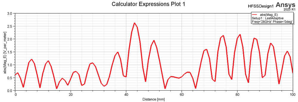
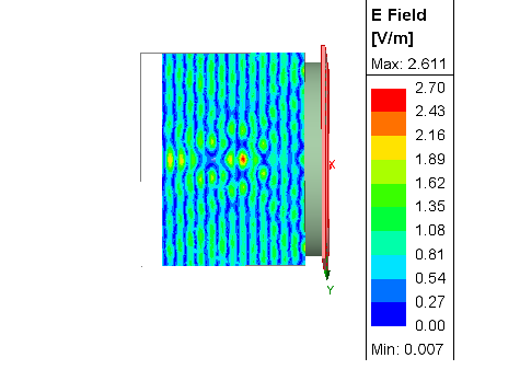
In ANSYS Electromagnetics Suite 2023 R1, a Fresnel Zone Plate is illuminated by a planar wave to approximate far field EM-wave incidence. The simulation results are shown in ILLUSRATION 5-1 for one-dimensional results and ILLUSRATION 5-2 for three -dimensional results. From these two figures, we could see that E-field reaches its maximum at 4.2 cm near theoretical focus (4 cm), which is amplified 3.574 times and our device could provide about 11.1 dB gain by power. Therefore, there is a good chance that our design will achieve the final goal of increasing the strength of the signal.
ILLUSRATION 5-1 Simulation Result of Fresnel Zone Plate(1D)
ILLUSRATION 5-2 Simulation Result of Fresnel Zone Plate(3D)
5.2 Simulation of Metamaterial Lens
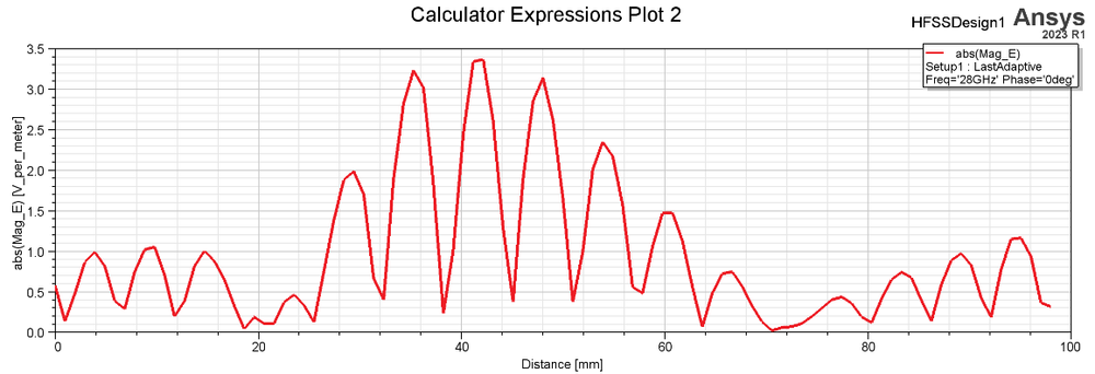
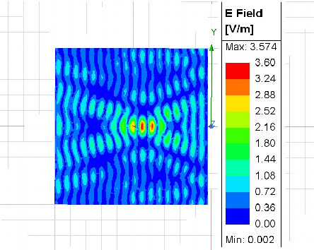
In ANSYS Electromagnetics Suite 2023 R1, a Metamaterial Lens is illuminated by a planar wave to approximate far field EM-wave incidence. The simulation results are shown in ILLUSRATION 5-3 for one-dimensional results and ILLUSRATION 5-4 for three -dimensional results. From these two figures, we could see that E-field reaches its maximum at 4.1 cm near theoretical focus (4 cm), which is amplified 2.611 times and our device could provide about 8.3 dB gain by power. Therefore, there is a good chance that our design will achieve the final goal of increasing the strength of the signal.
ILLUSRATION 5-3 Simulation Result of Metamaterial Lens(1D)
ILLUSRATION 5-4 Simulation Result of Metamaterial Lens(3D)
-
Conclusion
Chapter Six Conclusion
6.1 Problems and Solutions
The problem addressed in this project pertains to the design and implementation of a compact and cost-effective lens-based beam-forming millimeter-wave (mm-wave) antenna. The conventional approaches in antenna design have relied on printed technology, which can achieve high gains but necessitate complex and expensive feeding networks. Lens antennas offer a promising alternative due to their ability to eliminate the need for intricate feeding networks at targeted frequencies. However, their manufacturing has been challenging, mainly due to their intricate geometries and the requirement for specific refractive index materials.
The project seeks to overcome these manufacturing difficulties by leveraging the advancements in 3D-printing technology, particularly at the 28 GHz frequency band. The use of low-loss dielectric and conductive filaments, along with the improved precision and reduced costs of modern 3D-printers, enables the realization of high-frequency topologies that were previously economically unfeasible. By designing and producing 3D-printed Fresnel Zone Plate and Metamaterial Lens antennas, the project aims to demonstrate the feasibility of cost-effective and easy manufacturing of lens antennas.
6.2 Outcomes
The accomplishments presented herein are primarily predicated on the stipulated requisites put forth by our corporate entity. As delineated by our patron, our design endeavors are mandated to adhere to a set of specified requirements, encompassing signal gain, signal bandwidth, signal frequency, and signal scanning range.
Concerning signal gain, the prescribed criterion necessitates a minimum of 3 dB gain. Our two devised solutions, namely the Fresnel Zone Plate and Metamaterial Lens, respectively exhibit gains of 8 dB and 10 dB. In regards to signal frequency, the designated operating range is between 26 to 30 GHz. Consequently, our implemented designs have been thoroughly assessed at a frequency of 28 GHz. Furthermore, our designs aptly demonstrate a bandwidth of 1 GHz, effectively meeting the established requirements in this regard. Addressing the signal scanning range, compliance calls for coverage within the bounds of -40o to 40o. Through rigorous testing, it has been ascertained that the beam width of the Metamaterial Lens at 10 dB is 23.2o, whereas that of the Fresnel Zone Plate stands at 18.52o.
Regarding the manufacturing aspects, both the Fresnel Zone Plate and Metamaterial Lens configurations conform to a size constraint not exceeding 10 cm * 10 cm. The precision of our manufacturing equipment amounts to 0.1 mm, which amply suffices for millimeter wave applications.
With respect to cost considerations, the budgetary constraints dictate that the expense associated with each of the two designs must not surpass 100 RMB. Evidently, the unit price of printing constitutes a notable contributing factor. However, should the designs be subjected to mass production, the unit cost is expected to remain below 30 RMB, thereby rendering the overall proposition economically feasible and cost-effective for an antenna application.
-
Acknowledgement
Acknowledgements
Sponsor: Qin Wang, Wei Zhao, Lijing Huang from Sunway
Prof. Xuyang Lu, Jigang Wu, Guolin Tong from UM-SJTU Joint Institute
-
Reference
References
[1] M. Imbert, A. Papió, F. De Flaviis, etal. Design and Performance Evaluation of a Dielectric Flat Lens Antenna for Millimeter-Wave Applications, in IEEE Antennas and Wireless Propagation Letters, vol. 14, pp. 342-345, 2015, doi: 10.1109/LAWP.2014.2363596.
[2] Zhang Long, Zhao Hui, Hou Shuai, etal. A Survey on 5G Millimeter Wave Communications for UAV-Assisted Wireless Networks. in IEEE Access. PP. 1-1. 10.1109/ACCESS.2019.2929241.
[3] N. J. G. Fonseca, Q. Liao and O. Quevedo-Teruel. Equivalent Planar Lens Ray-Tracing Model to Design Modulated Geodesic Lenses Using Non-Euclidean Transformation Optics, in IEEE Transactions on Antennas and Propagation, vol. 68, no. 5, pp. 3410-3422, May 2020, doi: 10.1109/TAP.2020.2963948.
[4] Kim, Chiyen. 3D printed electronics with high performance, multi-layered electrical interconnect. IEEE Access 5 (2017): 25286-25294.
[5] Cuevas, Matias. Parametric study of a fully 3D-printed dielectric resonator antenna loaded with a metallic cap. IEEE Access 9 (2021): 73771-73779.
[6] O. Bjorkqvist, O. Zetterstrom and O. Quevedo-Teruel. Additive manufactured dielectric Gutman lens, Electron. Lett. (2019).
[7] H. Pablo Zapata Cano, Z. D. Zaharis, T. V. Yioultsis, etal. Pattern Reconfigurable Antennas at Millimeter-Wave Frequencies: A Comprehensive Survey, in IEEE Access, vol. 10, pp. 83029-83042, 2022, doi: 10.1109/ACCESS.2022.3196456.
[8] R. Sauleau, C. A. Fernandes and J. R. Costa, Review of lens antenna design and technologies for mm-wave shaped-beam applications, 11th International Symposium on Antenna Technology and Applied Electromagnetics [ANTEM 2005], Saint-Malo, France, 2005, pp. 1-5, doi: 10.1109/ANTEM.2005.7852157.
[9] P. Padilla, A. Muñoz-Acevedo, M. Sierra-Castañer, etal. Electronically reconfigurable transmitarray at ku band for microwave applications, IEEE Transactions on Antennas and Propagation, vol. 58, no. 8, pp. 2571–2579, 2010. doi:10.1109/tap.2010.2050426
[10] C. Ma. Implementation of a 2-D reconfigurable Fresnel-Zone-plate antenna, IEEE Transactions on Antennas and Propagation, vol. 69, no. 1, pp. 520–525, 2021. doi:10.1109/tap.2020.3008066
[11] D. R. Reid and G. S. Smith. A full electromagnetic analysis for the Soret and folded zone plate antennas, IEEE Transactions on Antennas and Propagation, vol. 54, no. 12, pp. 3638–3646, 2006. doi:10.1109/tap.2006.886564
[12] A. H. Abdelrahman, F. Yang, A. Z. Elsherbeni, and A. Khidre. Transmitarray antenna design using slot-type element, 2013 IEEE Antennas and Propagation Society International Symposium (APSURSI), 2013. doi:10.1109/aps.2013.6711337
[13] Zhang, S. (2016). Design and fabrication of 3D‐printed planar Fresnel Zone Plate Lens. Electronics Letters, 52(10), 833–835. https://doi.org/10.1049/el.2016.0736
-
VM495 Abstract
ABSTRACT
5G mobile communication technology brings significant advancements compared to 4G, such as ultra-fast data rates, minimal latency, and improved spectral efficiency, by utilizing the millimeter-wave spectrum. Compared with printing-technology based patch array, lens antenna has simpler structure, lower dielectric and conductive losses,, while remains the capability of beam-forming by constructive interference. The purpose of this paper is to design compact and low cost antennas lens-based beam-forming antennas for millimeter wave.
In this paper, technology and designs on lens-based millimeter-wavelength beam-forming antennas are reviewed. Among reviewed technologies, two antenna concepts, namely Fresnel Zone Plate and Metamaterial Lens stand out as the solution which offers high amplification and angular selectivity at working frequency 28GHz. The first design is a metal based Fresnel Zone Plate with radius 53.5 mm and provides 10.1 dB gain and a 18.2o 10 dB beamwidth. The second design is a 3D printing PA12 based Metamaterial Lens with radius 50.1 mm and provides 8.1 dB gain and a 23.2o 10 dB beamwidth. The measured results also fit well with the simulation in Ansys HFSS, which suggests 11.1 dB gain for the Fresnel Zone Plate and 8.3 dB gain for the Metamaterial Lens. Particularly, the Metamaterial Lens utilizes the Material Porosity Method to achieve permittivity control on homogeneous medium. The cost of the antennas are 160 RMB and 290 RMB for Fresnel Zone Plate and Metamaterial Lens respectively, which can be further significantly reduced in mass production. Therefore, this paper provides a cost-effective and efficient solution for 5G communication and millimeter-wave applications.
Key words: millimeter wave antennas, Fresnel Zone Plate, Metamaterial Lens, beam-forming, micro-manufacturing