Student Projects
Multi-functional Screwed Propelled Vehicle
Project Video
Team Members

Team Members:
韩宇翔 Yuxiang Han,蒋子宸Zichen Jiang,贾宜静Yijing Jia,蘇逸安Yian Su, 李卓恒Zhuoheng Li,李明鉴Mingjian Li
Instructors:
Yanfeng Shen,Ting Sun
Project Description
-
Problem

The often uneven and rocky terrain of Mars makes landing on, and traversing, theplanet's surface a significant challenge.
The surface of Mars is extremely uneven, containing rocks, mountainous terrain, andcraters. For a landing craft, the ideal landing area would be flat and debris-free.Since this terrain is almost impossible to find on Mars, landing gear must bevery stable and have enough ground clearance to prevent problems with tippingover and instability upon landing.
Therefore,adaptable dynamical system, stable underpan and balanced weight distributionare needed.
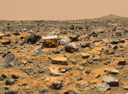
Figure 1. Sandy and Rocky Land On Mars
-
Concept Generation
1.1 Mars Rover Overview
The Mars Exploration Rover mission is part of the Mars Exploration Program, a long-term effort of robotic exploration of the red planet. Primary among the mission's scientific goals is to search for and characterize a wide range of rocks andsoils that hold clues to past water activity on Mars. After the airbag-protected landing craft settled onto the surface and opened, the rover srolled out to certain locations to perform on-site scientific investigations.
A Mars rover is a motor vehicle designed to travel on the surface of Mars. Rovers have several advantages over stationary landers: examine more territory, be directed to interesting features, place themselves in sunny positions to weather winter months, and advance the knowledge of how to perform very remote robotic vehicle control.
The four science goals of the long-term Mars Exploration Program are: Determine whetherlife ever arose on Mars, Characterize the climate of Mars, Characterize thegeology of Mars, and Prepare for human exploration of Mars.
1.2 Basics of Screw-Propelled Vehicles
Vehicles with wheels, continuous tracks or legs are commonly utilized in different engineering tasks. Screw-propelled vehicles are rare. Such vehicles employ atleast one drive screw as a way of movement. Drive screw is as a rule a cylinder with a helical blade, comparative to screw string, which can pivot around its longitudinal axis. The most broadly used configuration utilizes two parallel drive screws with inverse helix directions (one helix is clockwise, whereas theother is counter-clockwise). Design of a screw-propelled vehicle plans isn't restricted to the two screw setup. Whereas numerous screw-propelled vehicles use a number of sets of drive screws, there are moreover vehicles that employan odd number of drive screws, as well as vehicles using both drive screws andother implies of motion, such as wheels, slips or ceaseless tracks. A few ofthe plans make it conceivable to change orientation of the drive screws with regard to vehicle’s frame in order to enhance the maneuverability. Screw-propelled vehicles are able to operate in difficult environments. A few of the plans areland and water proficient, which allows them to function in water, with drivescrews working in a comparable way to boat propellers. Screw-propelled vehiclesusually create a high tractive force. Another feature may be a basic plan andlow number of moving parts, particularly when compared with other means of motion in troublesome territory, such as tracked vehicles. The most drawbacksof screw-propelled vehicles are low maximum speed and high power required dueto critical energy losses. Moreover, such vehicles are difficult to operate onrigid surfaces and can possibly damage surfaces they move on.192 D. Osiński andK. Szykiedans The most notable screw-propelled vehicle is the RussianZiL-29061. The ZiL was designed in 1970s as a rescue vehicle for cosmonauts that landed in inaccessible areas. Nowadays, Australian vehicle MudMaster is used as a mean of dewatering and densification of soil. The three vehicles are similar in size to a truck. Smaller screw-propelled vehicles have also beendeveloped. Spiral Track Autonomous Robot designed at Lawrence Livermore National Laboratory is a survey vehicle intended to operate in hostile environments. The Screw Drive Rover, developed at the Graduate University forAdvanced Studies (Sokendai) in Japan was used as a help in validating simulation of interaction between soil and drive screw. Remotely controlled screw-propelled vehicle was presented by Tyco toy company under the name ofTerrain Twister. All of the mentioned vehicles employ configuration of two parallel drive screws. Russian company Tesh is working on improving the operation of screw-propelled vehicles on rigid ground by combining the drivescrews with rubber tires. When the vehicle is operating on soft soil, the tiresare deflated and the helixes of drive screws are in contact with the ground.The tires can be inflated to work on rigid ground like standard tires.
-
Design Description
We designed the screw-propelled vehicle into two components: A robotic arm and screw-propelled vehicle. First,we determined the shape of the vehicle being rectangle. To make it be able to move in all direction, we used four separate screws to serve as wheels. Then weadopted Arduino board and motor expansion control panel to control the vehicle and use four batteries to power the device. Then we installed program which allowed the device to be controlled through Wi-Fi connection by smart phone application.Taking the convenience of repairing into consideration, we used modular design which enabled us to restore broken part without disassembling the entire machine. To achieve this, we decided the size of each components to ensure that they can be assembled perfectly.
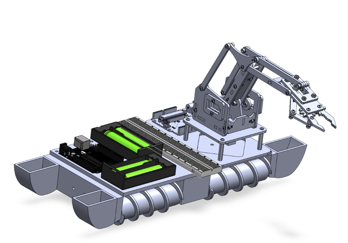
Figure 2. Overall View of Vehicle
-
Validation
We tested the screw-propelled vehicle in multi-environments with different parameter settings.
√ [1] We first put it on solid ground.The vehicle showed outstanding stability and flexibility. Then by adjusting some parameter of four motors, the rotation speed and direction of the four propellers can be controlled precisely to finish different movements. Also, it can overcome small obstacles and maintain
the previous moving track.
√ [2] We tested it on sandy and rocky ground with slopes. However, due to the restricted power
the motor, the vehicle has some difficulty moving smoothly. It indicates that our prototype still needsiteration and should change for motor with bigger power output.
-
Modeling and Analysis
1.Design procedure
1) Determinethe main shape and outlook
We first determined the shape of our screw-propelled vehicle being rectangle. To make it be able to move in all direction, we use four separate screws to serve as wheels. To make the vehicle steadier, the side of the screw cylinders is designed to be partially exposed outside the cover of the main board.
2) Determinethe needed components
Then we decided all the necessary parts: a main board for Arduino board, two battery boxes, one breadboard and one robot arm, a base to support the main board and screws, and front and back board to support screws and put motors. We drew a draft to showhow to assemble these components.
3) Determinethe detailed size of the components
Then we decided the sizeof each component to make sure they can be easily assembled without confliction.
2. Componentdesign
1) Mainboard
The main board is fixed above the screws to fix one Arduino board, two battery boxes, one breadboard and one robot arm. The robot arm is fixed at the back part of the main board,and the holes on it are used to screwed the robot arm base to the main board.The breadboard is next to it. The Arduino board and two battery boxes are atthe front part of the main board.
2) Base
· The base of our screw-propelled vehicle is cross-like when it is looked down from the above.
· There are four holes on the wall of the short side of the cross-like base. These holes are respectively used to put the rotation role of each screw.
· There are two holes side by side on the front wall of the cross-like base and also two other holes on the back wall. These holes are for screwing the front and the back board to the base.
3) Front and back board
The front and the back board of our screw-propelled vehicle are the same. They both have two small containers at the edge and on the box wall there is a hole to let motor role andscrew axle through. There are also two small holes side by side in the middle,which are used to screwed to the base, as is mentioned above.
4) Screw
Each screw has anaxle. One end of the axle is thinner than the other end. The thinner end is tobe inserted into the hole on the short side wall of the base, while the thicker end is hollow with a half-moon-shaped hole to insert the motor role, to be inserted into the hole on the front and back board.
-
Conclusion
The screw-propelled vehicle can conquer various harsh terrains on the Mars and collect samples from the Mars.However, due to the limited power of the motor, the vehicle has some difficulties moving smoothly. As for the robotic arm, it can be controlled by Wi-Fi remotely and has multiple degrees of freedom control.
-
Acknowledgement
The completion of this project could not have been possible without theparticipation and assistance of our groupmembers contributing to this project. As a team, we are highly indebted to Professor Shen and Professor Sun for their guidance, instruction, and inspiration. We would like to express our gratitude towards our friends for their kindco-operation and encouragement which help us a lot in completing this project.Our thanks and appreciations also go to JI for supporting us with the material.Thank you to all the people who have willingly helped us out with your abilities.
-
Reference
Osiński, D., Szykiedans, K., “Small Remotely Operated Screw-Propelled Vehicle,” Springer, 2015. doi:10.1007/978-3-319-15847-1_19